


The thermocouple (TC) is a thermo-electric device used to measure temperature and nearly two-thirds of U.S. temperature measurement makes use of thermocouples. Most industrial applications use a TC to remotely sense temperature and then transmit its signal some distance using TC transmitters to monitor and control a process. The TC transmitter amplifies, isolates, and converts the low-level signals to another signal suitable for monitoring and retransmission. Unfortunately, the interface between the TC and mating instruments is widely misunderstood, which often leads to measurement error. The focus of this paper is on the connectivity aspects of thermocouples and TC transmitters to reduce error that can be extended to include connection to any thermocouple instruments.
A TC is formed using a pair of different metal wires joined at one end (referred to as the hot junction). At the opposite open end of a pair of wires (its cold or reference junction), a low-level voltage proportional to the difference in temperature between the ends can be measured. Of available temperature sensors, the TC has the widest application range giving accurate measurement of extreme temperatures in harsh environments. To extract the hot end temperature from measured TC voltage related to the difference, it is necessary to measure the temperature at the open end to determine the temperature at the other end (the hot junction). Because the TC voltage is not linear with temperature, its conversion from voltage to temperature normally requires a complex polynomial specific to the thermocouple type, or optionally determined using a standard lookup table of TC voltage versus temperature. Originally, TC voltage was tabulated while holding its reference junction in an ice bath corresponding to 0°C (hence the term cold junction). Modern thermocouples still reference themselves to a cold junction of 0°C with their standard table tabulating output voltage over temperature with respect to 0.000mV at 0°C. The use of standard TC tables and a simple correction can reduce this polynomial conversion from voltage to temperature to a combination of measured and tabulated voltage (more on this later).
The nature of the TC circuit is that it is prone to produce error when mating it to a measurement device without some insight into how these thermocouples and TC components work. This paper reviews TC behavior and outlines common problems encountered when connecting to thermocouples to measure temperature to help you avoid error and get the best possible performance from your TC temperature measurement system. It is written primarily for industrial users of thermocouples and TC transmitters, but much of this information can be extended to any thermocouple instrument. For more comprehensive information about thermocouples, please refer to whitepaper 8500-911, The Basics of Temperature Measurement Using Thermocouples, available free for download from www.acromag.com.
Building a Thermocouple
Thermocouples were developed from a principle first demonstrated in 1822 by German physicist Thomas Seebeck when he observed that the application of temperature along a metal conductor drives charge separation in the conductor such that a small voltage is developed across it (Figure 1). Using two different metals joined at one end to create an open-circuit loop, he was able to measure this thermo-electric effect and relate the voltage seen at the open end to the temperature difference between ends. This effect is only evident for two different metals and different combinations produce different voltage levels for the same temperature difference. This was later coined as “The Seebeck Effect” and the Seebeck Coefficient of various materials remains a measure of the magnitude of this voltage generated by a temperature difference across the material. The Seebeck coefficient has units of Volts per Kelvin (V/K), or microvolts per Kelvin (uV/K), and is inversely related to the material’s current carrier density, such that insulators will have a high Seebeck coefficient, and metals will have a lower coefficient due to their higher carrier concentration.
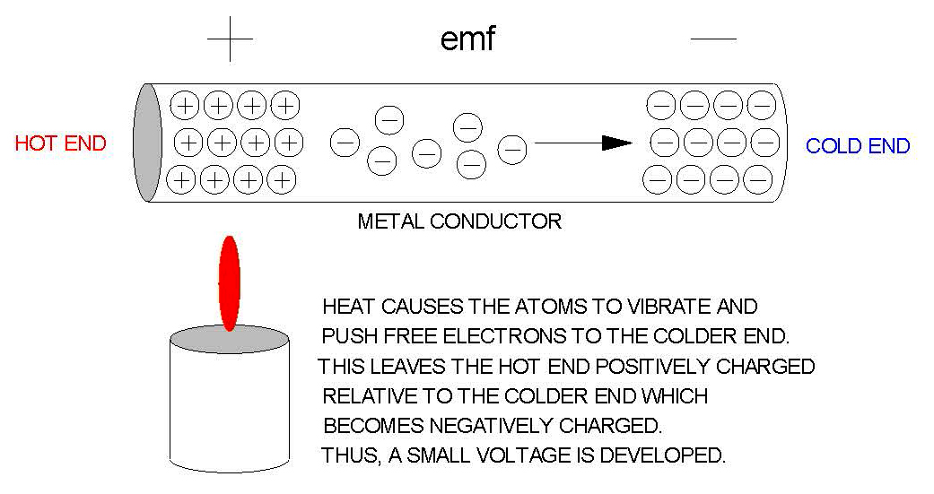
Referring to Figure 1, by applying heat to one end of a conductor, the atoms that make up the metal will vibrate rapidly and the kinetic energy of the vibrating atoms spreads along the wire and conducts heat from the hotter end to the colder end. These rapidly vibrating atoms at the hot end of the metal drives free orbiting electrons to the colder end, leaving it more positively charged. The magnitude of this charge separation or voltage difference varies only with different material types such that its length or gage has no effect on the voltage magnitude. Because different materials produce different degrees of charge separation for the same temperature difference, tying two different conductors together at one end drives a net voltage difference measured at the open end and is directly proportional to the difference in temperature between the ends. By tabulating this voltage difference for various imposed hot-end temperatures while its cold end is held at a steady reference temperature, the relationship between the thermoelectric voltage and sensed temperature can be derived.
The most important thing to remember about the TC is it that it’s the temperature difference between ends that produces the charge imbalance that drives the small voltages, not the junction of the two dissimilar metals that form the thermocouple circuit. While you can form your own TC circuit with different combinations of two conductors, standard TC types using specific metals and alloys are available that produce larger, stable, and predictable output voltages relative to applied thermal gradients. These standard types have their voltage over temperature tabulated in TC type tables relative to a cold junction at 0°C and 0.000mV. These TC voltages could have been referenced to another temperature than 0°C, but 0°C was chosen because it is easily reproducible within ±0.2°C using a mixture or slurry of ice and water. By holding the cold junction at 0°C, the temperature of the other end directly corresponds to its thermoelectric voltage found by look-up in the standard TC type table.
Three Fundamental Principles of Thermocouples
To correctly apply thermocouples to temperature measurement, it’s important to understand three thermoelectric principles that govern TC behavior and that give important clues for properly conditioning them.
The first basic principle is The Law of Homogeneous Materials (see Wikipedia.org): A thermoelectric current cannot be sustained in a circuit composed of a single homogeneous material by the application of heat alone, and regardless of how the material may vary in cross-section.
This tells us:
- No current flows in a conductor circuit by the application of heat alone when made of a single metal.
- Two different metals are required to form a thermocouple.
- The size or gage of wire does not affect the voltage produced.
- The voltage produced is independent of temperature variations along the TC path.
The TC produces a voltage difference between ends independent of the temperature distribution along its length allowing you to pass TC wires through hot and cold areas without affecting its measurement if the wire material is kept consistent along the wire path (i.e. using TC connection blocks & extension wires).
The second principle that governs TC behavior is The Law of Intermediate Materials (see Wikipedia.org): The algebraic sum of the thermoelectric EMFs in a circuit composed of any number of dissimilar materials is zero if all the junctions are maintained at a uniform temperature.
This tells us:
- If a different metal than the TC material is used to connect either or both TC wires, the measured voltage will not be affected if the different metal is kept at the same temperature across its transition or isothermal.
Extending this principle to the cold junction at the open end of a TC circuit where the measurement is taken (inclusive of the lead metal, solder, copper board traces, etc.), it may be considered isothermal when its combined temperature remains constant, usually following a period of heat exchange with its surroundings where its temperature may adjust slowly over time before finally reaching thermal equilibrium (its warm-up period).
The third principle that governs TC behavior helps us combine TC voltages mathematically using standard tabulated values taken with respect to the same reference is referred to as “The Law of Successive or Intermediate Temperatures” (see Wikipedia.org): If two dissimilar homogeneous materials produce a thermoelectric voltage V1 when its junctions are at T1 and T2, and then produce thermoelectric voltage V2 when the junctions are at T2 and T3, then the voltage produced when the junctions are at T1 and T3 will be V1 + V2, as long as T1<T2<T3.
The behavior of a TC type is normally characterized by a 5th or higher order polynomial used to calculate its voltage versus temperature in its standard table. The Law of Successive or Intermediate Temperatures allows you to instead accomplish cold junction compensation of the TC measurement by subtracting the TC voltage of the cold junction temperature from the measured voltage to get the actual voltage that corresponds to the hot end of the TC circuit. This is illustrated graphically in Figure 2.
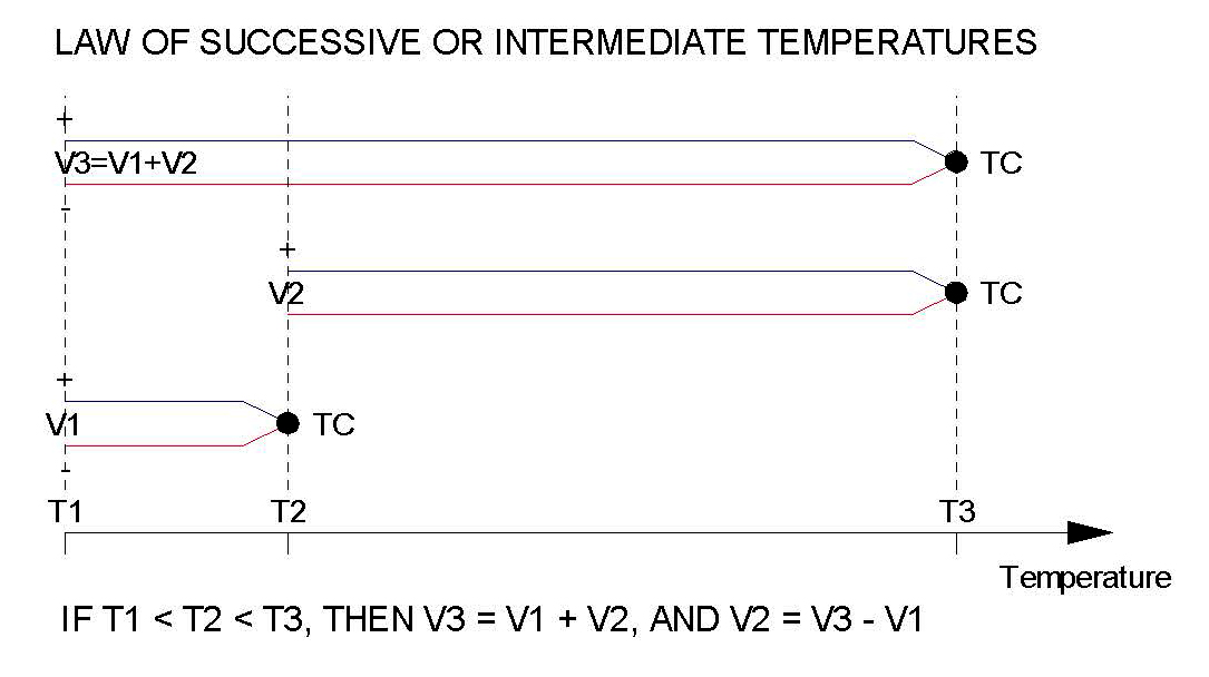
In practice, temperature T3 is unknown and the cold junction temperature is not 0°C. You have the measured voltage V3. If you also measure the temperature at the cold junction T1 and look up its equivalent voltage V1 relative to T2=0°C in a TC type standard table. By subtracting V1 from your measured V3, you can determine V2. Then the temperature T3 can be matched to the voltage V2 by referring to the TC standard voltage versus temperature table.
The Cold Junction and Cold Junction Compensation
You should be aware of how a TC instrument accomplishes cold junction compensation, the limits it imposes on your measurement, and potential conditions that can increase CJC error.
Briefly, we’ve shown that the open-end thermo-electric voltage measured across a thermocouple is only related to the difference in temperature between the ends. To determine the temperature at one end, we need to know the temperature of the opposite end. Cold Junction Compensation simply refers to the method we use to extract the measured temperature by determining the cold junction contribution to get the remaining portion that corresponds to our measured temperature when the cold junction temperature is not 0°C. Briefly, applying cold junction compensation to the open end helps us extract the sensed temperature at the other end (hot junction) from our measured voltage. Of course, if the connections at the open end are kept at 0°C, its contribution to the measured voltage is 0mV, allowing us to easily determine the sensed temperature via simple lookup of the voltage in the TC type standard voltage/temperature table. In practice, keeping the open end at 0°C is not easily accomplished. Instead we can measure its temperature, determine its voltage contribution in the TC type look-up table, then subtract it from the measured voltage and look up the corresponding temperature for the resulting voltage in the standard TC type table.
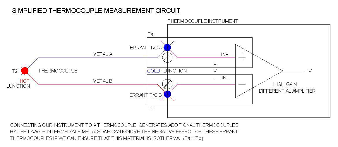
The Law of Intermediate Materials says that the sum of the thermoelectric voltages in a TC circuit created by any number of different metal junctions will be zero, if each of the metal-to-metal junctions can be maintained at the same temperature or isothermal through their connection. Maintaining all these metal elements at the same temperature or isothermal can be very difficult to accomplish, especially if they extend some distance, or are individually subject to other thermal influence that may unevenly affect their temperatures. Keeping inadvertent thermocouples isothermal cannot be completely avoided, but we take precautions to keep their contribution small by limiting varying temperatures influences on them. Manufacturers of TC instruments with cold junction compensation have two challenges:
- Make the CJC circuit isothermal as quickly as possible by closely coupling the TC wire connection points to keep them subject to the same temperature–any uneven temperature gradient between the point pairs will be a source of error.
- The temperature of the CJC connection points must be measured at least as accurate as the TC itself. The response time of the CJC temperature sensor is also a factor in maintaining accuracy for systems that require a fast response, as the cold-junction is often subject to unstable ambient conditions (like nearby board components that dissipate power unevenly or unstable air currents).
The performance of a TC transmitter is reflective of how well the manufacturer was able to accomplish CJC and this usually requires some compromise. For example, the transmitter may require a longer warm-up time, making it vulnerable to temporary error driven by quickly changing temperatures or power conditions near the junction. It may not measure its cold junction temperature as accurately as the thermocouple, or with equivalent resolution, increasing measurement uncertainty. But more often, poor installation practices in the use of this equipment increases CJC and measurement error making it one of the greatest sources of thermocouple measurement error.
The Law of Intermediate Materials allows thermocouple connections using other metals without affecting the measured value if the “other metals” if their connections are kept at the same temperature or isothermal. To resolve the TC voltage measured to the hot junction, the instrument must measure the temperature of its “isothermal” cold junction circuit accurately and achieved accuracy of the measurement is only as good as the accuracy of its measured cold junction temperature.
A simplified thermocouple circuit including the cold junction is illustrated in Figure 3.
Ideally, TC instruments should have a short warm-up time with fast cold junction compensation and closely couple their CJC sensor to the cold junction terminals, or use terminals made of a compatible TC material. Because many instruments mount the CJC sensor on the circuit board with the cold junction connections outside the enclosure. Some manufacturers try to embed the CJC sensor in the bulk of the terminals (usually its plastic) or locate the sensor as close as possible to the terminals mounted to its circuit board. Both approaches limit the ability to precisely measure the real temperature of the cold junction connections and this is sometimes reflected in the specifications which may indicate increased error with CJC on, or only specify accuracy with CJC off. Some manufacturers avoid CJC error by using cold junction terminals made of the same material as the TC to push the cold junction down to the circuit board in closer contact with an on-board temperature sensor.
Unfortunately, that makes the instrument TC type-specific and the junction is still vulnerable to board heat source variations driven by other board components. The reality is that these instruments come in many sizes, shapes, and styles such that their construction often involves tradeoffs that affect their CJC relative to cost and performance. Be aware of the potential problem areas to help minimize CJC error.
The single best way to make cold junction connections with other metals is to minimize the distance between the metals, balance their thermal masses, and reduce the thermal resistance between them (i.e. we want heat to be evenly distributed across them). Anything that can drive a difference in temperature in the circuit between and including the cold junction connections will add error to the measurement.
As an installer, protect the cold junction terminals from anything that can drive a temperature difference between them or force an uneven distribution of heat across them. This usually involves shielding them from unstable ambient conditions near the cold junction connections and across its circuit. Always consider potential sources of varying temperature and try to make the thermal conditions near the cold junction more stable. This could require added shielding, or simply rearranging the position of equipment. Look for adjacent sources of heat (power supplies, other modules, etc.), vents, and cooling fans, etc. Focus on items that operate intermittently or with variable power dissipation. While it may not be possible to eliminate items, you can take measures that minimize their influence on the cold junction. For example, you might locate the measuring instrument (or at least its cold junction terminals) outside of the air stream of a cabinet cooling fan. You can sometimes add space between instruments and adjacent heat sources. Look at the mounted position of an instrument relative to its vents—is it positioned in such a way that it cannot easily release hot internal air? Be careful in routing sensor leads to the instrument and make sure that at the point you break out the TC leads prior to a connection, that one lead is not subject to a source of heat that causes its lead to conduct heat to its cold junction connection and upset its thermal balance across the cold junction. Avoid introducing other inadvertent thermocouples to your TC loop. For example, have you selected external terminal blocks that match the TC or have you substituted less expensive isotherm blocks that require you to maintain the same temperature through them (adding one more path for inadvertent thermocouples that can negatively affect your measurement if you can’t keep them isothermal)? Have you shared a terminal with one TC lead such that this adjacent wire may be heat sinking the TC lead and upsetting its thermal balance across the cold junction? Small thermal gradients across the cold junction circuit may also occur due to self-heating of nearby board components. Also consider changes to the operating state of the instrument that might drive changes in internal power dissipation which will acts on the CJC sensor sharing that space.
The cold junction connections and its sensor needs more time to reach thermal equilibrium, causing periods of increased measurement error immediately following changes in ambient conditions. Be sure to consider potential sources of error when making TC instrument connections related to the fact that cold junction ambient temperatures are tracked slowly relative to the fast response time of the TC hot junction. This lag can result from the larger thermal mass of the connectors and poor thermal coupling to the CJC sensor. While a slow responding cold junction does tend to filter out some rapid changes in cold junction ambient, it does not prevent the slow progression of an instrument to an accurate measurement after a notable shift in cold junction ambient.
Potential error related to CJC is evident by long warm-up times specified for TC instruments. Measurement accuracy generally improves as a change in cold junction ambient is absorbed by the CJC materials and its heat is more evenly distributed across its connections to the cold junction sensor. For example, if someone suddenly opens a cabinet door and hot air contained rushes out, causing a rapid shift in cold junction ambient to shift temporarily throwing off the measurement until a new thermal equilibrium can be reached. Or perhaps, a fan is operated intermittently inside the cabinet causing an ambient to shift. For thermocouple transmitter or instrument connections that include cold junction compensation, it might take from 30-60 minutes to reach a new thermal equilibrium. When assessing a temperature measurement system for the presence of these conditions, keep in mind that a shift in operating ambient can also be sourced by the circuit itself — Has its operating state changed abruptly affecting its internal power dissipation? For a loop-powered 2-wire transmitter, this would be true if the external load being driven has been reduced or shorted, or if the power supply voltage has changed or is excessive relative to what is required to drive the load.
Some instruments allow you to disable cold junction compensation and doing so can give some indication of how much error is being contributed due to “thermal gradients” acting on CJC. When resolving these errors, review the module placement and position, adjacent influences, your wiring, etc. In addition to conditions that magnify CJC error, other real sources of measurement error often involve poor choices of connection materials like wire, cable, and terminals and thermocouple routing errors to the transmitter.
Connection Materials
The materials you select to connect a thermocouple will impact the accuracy of your system (terminal blocks, thermocouple wire and cable, and extension cable).
Terminal Blocks
Thermocouple wires are designed to be fine to help prevent their mass from affecting the temperature being sensed making them delicate and subject to breakage. While TC instrument manufacturers often provide wiring diagrams showing thermocouples wired to cold junction terminals on the instrument, this is often not the case. Industrial applications typically use TC terminal blocks separate from the instrument to mate to the TC leads with TC wire and extension cable connecting the terminals on the transmitter. These extra terminals often serve as a strain relief and facilitate easy change-out of a failed instrument or sensor. Unfortunately, offsetting TC connections from the instrument adds another potential source of error usually related to the choice of terminals. Users not familiar with the Law of Homogeneous Materials or The Law of Intermediate Metals may incorrectly choose standard terminals that subject TC leads to errant thermocouples that result from thermal differences that develop across the extra junctions. It is important to use terminal blocks designed specifically for the thermocouple type to avoid adding error and there are three main types of TC terminal blocks uses that come in many physical varieties. Most are DIN rail mounted and some may include a special socket for connecting the plug of a hand-held meter designed to monitor thermocouple voltage.
The best type of TC connector uses connection materials the same as the TC metals, or of a compatible alloy. By the Law of Homogeneous Materials, use of this in the wired path will not affect the voltage measurement because it matches or mimics the material of your TC leads. Any temperature variation through this other material has no effect on the measured TC voltage and operates transparent to the TC wire. Of course, these connectors are more expensive since they TC type specific. Any error resulting from their use is usually attributed to mismatching them to the TC type or flipping their polarity. In the U.S., the body color of a TC connector closely matches the outer insulating sheath of the TC type.
The next best TC connector is the “universal” type. Universal types do not use connection metals that match the TC leads, making them less expensive. Universal types instead try to closely couple the ingress and egress wires with little or no intermediate material contact to create an isothermal union to the TC and mimic a homogeneous connection. In this type, the input TC wire enters one end and the output TC wire exits the opposite end. The two wires overlap for some length inside the connector and make good thermal and electrical contact, usually without passing through an intermediate metal. Two clamping screws and a common pressure plate are used to secure the wires. As a result, the negative effect of using non-homogeneous material is minimized.
The least expensive universal type is designed to equalize the temperature across the union and is sometimes referred to as an “isotherm block.” This type of connector exploits the Law of Intermediate Materials to allow other metals to connect the TC circuit but not affect the measurement by attempting to keep the material isothermal or at the same temperature. For example, its wire screws are usually recessed to shield them from air drafts and its plastic housing is designed such that its input and exit paths are closely spaced. These blocks do make connection to the thermocouple using an intermediate metal, and they are less favorable because they rely on maintaining the same temperature through the material to minimize its effect on the measurement by limiting the contact length to an intermediate metal. And while they have a cost advantage and may be applied universally to any TC type, they do not form perfect isothermal unions and small voltage effects can develop, especially where the diameters of the mating wires differ, which is most often the case.
Because universal connector types may involve some intermediary contact, you should take precautions with both to ensure no difference in temperature between its wire input and output paths. Of course, for any connection type, error can be driven into the measurement due to the breakout they force between the individual TC wires from their sheath and from each other, which sometimes exposes one wire to a different temperature than the other, conducting its heat to the connection block and upset the isothermal balance across its non-homogeneous connection path. The breakout of the individual TC wires leaves a portion of the wire unshielded vulnerable to noise pickup—always keep the breakout length to a minimum. Some of these connection blocks will include screw connections for the TC cable shield which is helpful to extend the shield right to the instrument minimizing breakout exposure.
Perhaps the greatest concern of using any type of external terminal to connect the TC wires is to make sure that standard, non-thermocouple types are never used for this purpose, or have been inadvertently substituted, which drives errant thermocouple voltages into the measurement and reduces accuracy. Don’t try to justify use of cheaper standard blocks using the Law of Intermediate Metals, as these terminal use steel or a nickel-plated copper alloy for their contacts adding more errant thermocouples to your measurement. They only work if you can assure the temperature on both sides of the connection block remains the same or changes at the same rate —highly unlikely in a packed control cabinet full of warm equipment, cooling fans, or other devices that may heat or cool the interior ambient in an uneven way.
TC Extension Wire & Cable
To extend TC wire over long distances, less costly thermocouple extension cable is often used with TC terminal blocks to lower cost. These cables often have larger diameters up to 14 AWG and can be used to reduce loop resistance too. Extension cable will use similar materials to the TC, or materials better suited for the intervening environment along its path. But for extension cables, it’s important to remember that its thermal behavior may only approximate that of the TC and its insulation may restrict the TC to use over a smaller temperature range. Be cognizant of use of the extension and its potential limitations, as it can increase error if applied improperly with respect to temperature and environment. The extension wire conductors of base metal thermocouples (J, K, N, E, and T) usually matche the composition of the TC and exhibit the same thermoelectric properties. The extension wires of noble metal thermocouples (R, S, and B) are usually a different alloy which may only approximate the noble metal properties and over a more limited range. Their conductor materials are different because the noble metals contain platinum, which is very expensive to use as an extension over a long distance. The careful use of different materials is not usually a problem, as these noble metal types are mostly used at higher temperatures with lower resolution, making their different material error contributions less significant. But in all cases, the maximum application temperature is limited by the extension wire insulation and this is an important factor in their selection.
Potential measurement errors from using extension cables often result from poor connections driving errant thermoelectric voltages into the measurement, mismatching TC types, or reversing its polarity. You must use the correct TC extension cable type for the TC and observe the proper polarity. Substitution of any other type will increase measurement error. The same rules apply to mating connection blocks. Other problems may result by using extension cable of an incompatible material type for its environment, or where the extension wire is mismatched to the sensor or environment. For example, thermocouples that use iron metal will be subject to corrosion that may impede continuity, particularly in wet environments. Extension cable that does not match the TC type exactly will have a lower operating temperature range unsuitable for use close to the hot junction.
Thermocouple Sensor Wiring and Wire Routing
The path that you take in routing the sensor to the instrument will also impact measurement accuracy. Consider that the fine TC lead wires made from other materials than copper have a higher resistance than copper, making them more sensitive to noise pickup, especially AC-coupled noise. Additionally, because thermocouples output a low-level voltage, they have a low signal to noise ratio, higher conductor impedance, and most often connect to equipment that amplifies its signal, making long TC routes an easy pickup of errant noise signals from nearby equipment and power lines. Take measures in routing TC leads and extension cables that respect this sensitivity to noise pickup as follows:
- Route TC wires defensively and do not combine them with power wires. Operation in noisy environments or nearby electric motors may benefit from the use of screened extension cable.
- Avoid combining TC leads over long parallel paths with output or signal wires, which may inductively couple noise into the TC wires.
- Minimize the length or loop area where thermocouple cables or wires pull apart to make a connection to an instrument or TC terminal block.
- Individual wires can be twisted together to make sure both leads pick up the same signal (i.e. they reject common mode noise).
Note also that while the TC signals are small, much larger voltages may exist at the instrument due to the presence of common-mode voltages driven by inductive pickup along the sensor wire, or via multiple earth ground connections in the system. For example, inductive pickup is a common problem when using a TC to sense the temperature of a motor winding or power transformer. For some applications, multiple earth grounds may be inadvertent, perhaps when using a non-insulated or grounded TC to measure the temperature of a hot water pipe. In this instance, any poor connection to earth ground may drive a few volts of difference between the pipe and measurement instrument. These instruments often make use of high-quality, high-gain, differential instrument amplifiers that help reject noise common to both input leads as long for voltages within the common-mode input range of the amplifier, usually limited to only ±3V or ±5V by its internal DC voltage rail. This ability to reject common-mode noise is strong for signals near DC, but weaker as the frequency of the noise increases. It usually helps to twist the wires together to make sure that both leads pick up the same signal allowing any common mode noise to be rejected by the amplifier. Keep the lead length short and any loop area small where the cable wires part to make the instrument connection. For long runs, consider using screened cable with earth ground connected at the instrument end to minimize its noise pickup. There are different types of screened cable which include copper or mylar/aluminum tape, or even screened twisted pair if required. You have many options to combat noise pickup in a TC circuit and you may wish to consult with your cable vendor. The following link is a good resource for learning about other options in this regard: www.thermocables.com/faq.htm
Also consider that the junction of a TC sensor is commonly grounded and in direct contact with its surrounding case metal to give it a faster response time, but this can be troublesome for noise pickup and potential ground loop error which will significantly increase measurement error, often many times greater than the error contributed by the other influences we’ve reviewed. Ungrounded junction TC sensors are available where sensor isolation is required, but usually with an increase in response time. You may alternatively select an isolated TC transmitter for use with a grounded TC sensor to combat ground loop error.
A Review of Best Practices When Making Thermocouple Connections
Considering the TC connection carefully, CJC effects, plus the connectors and cables you use to increase your measurement accuracy:
Are the cold junction connections exposed to open air drafts that may unevenly distribute heat across them, such as that from heating or cooling-fans?
- Is the transmitter mounted inside the enclosure in a way that helps shield its cold junction connections from quickly varying air currents caused by movement of personnel and equipment, heating/air-conditioning fans, and outdoor air currents?
- Is the transmitter adjacent to a power supply or “warm” device that may cause one junction terminal to be warmed different from the opposite terminal, upsetting its isothermal balance? Are the individual leads of the TC wire fanned out of their sheath in a way that one lead may be subject to a different temperature than the other that could conduct heat to its cold junction?
- Have you observed proper polarity in connecting your TC sensor, any extension cables, and any matching TC terminal blocks? TC types are color coded and RED denotes Negative Lead for American or ANSI TC types. Sometimes this leads to confusion because it is opposite the convention used for DC power where red typically denotes positive.
- Have you allowed the transmitter up to 60 minutes of warm-up time after applying power to reach thermal equilibrium across its cold junction circuitry necessary for accurate cold junction compensation?
- Is the transmitter mounted in a position that curbs the flow of air across or through the unit that may increase its internal ambient? Are its vents blocked by adjacent modules, circuits, cables, or other obstructions? This can result in a larger internal ambient, increasing its potential for error driven by a longer thermal warm-up and wider temperature variation acting on the CJC temperature sensor inside the unit.
- Have you positioned modules in a way that allows air space between them to minimize the negative effect of adjacent heat sources on cold junction connections that might upset its isothermal balance? Are modules spaced farther apart from more significant sources of heat, such as power supplies, cooling fans, etc.?
- Have you spread the TC wires apart with a larger than required separation gap between them before they connect to terminals? If the cold junction terminals do not match the TC material, this breakout can drive a difference in temperature between the wires, where the individual leads route differently and may be subject to different temperature influences. This difference in temperature can act on the non-homogeneous cold-junction circuit upsetting its isothermal balance. Breaking the wires out of their shield also makes them more prone to noise pickup too. Sometimes a TC sheath is pulled back to individually tag the TC wires and while this looks nice, it opens the door for another potential source of error.
- Are you using crimp-on pins or terminals on TC wire ends to protect the wires inserted into the instrument? While this is done with good intention, this material is generally not the same as the TC and will effectively extend the cold junction by displacing it from its terminal and making its mass more vulnerable to developing a temperature across it. For some pin-style crimp-on connectors, the clamp of the cold junction terminals of the instrument will make contact over a smaller area and increase its thermal resistance. In general, you get better performance by simply connecting the TC wire or cable directly to the cold junction terminals of the unit. Most terminals are a cage-clamp style that already does a good job of protecting the wire and the use of additional crimp terminals is not necessary.
- Is one lead of the TC sharing a connection with another wire in the same terminal? The presence of this other wire can heat-sink the TC lead, driving a temperature difference across the cold junction that contributes error. Its negative effect is magnified if the adjacent lead is of a larger diameter than the TC wire causing it to act as a heat-sink ability and increasing the thermal resistance of the TC wire to junction contact. For example, some transmitter models may require that a TC break jumper be installed by sharing a terminal with one of the TC leads—keep this jump wire short and of a gage no greater than the TC wire to avoid increased error.
- Has a fault or other condition at the transmitter caused its circuit to increase or change its nominal power dissipation, affecting the heat distribution across the cold junction connections? For example, a two-wire temperature transmitter will dissipate more heat internally if its load resistance is reduced or shorted, or if its power supply is excessive relative to the level needed to drive the load.
- Make sure that any terminal block used in your TC circuit is not a standard type which will drive errant TC voltage into your measurement. TC connections should only use TC terminal blocks, or isotherm (universal) terminal blocks designed specifically for thermocouple connection.
- For multiple adjacent mounted instruments, but arranged from bottom to top (i.e. perhaps on a vertical DIN rail), consider the chimney effect of rising heat that will cause the units on top to be naturally heated by the units on the bottom, potentially affecting their accuracy, as this heat will be unevenly distributed across the cold junction connection circuitry? TC transmitters are typically designed with their input terminals positioned at the bottom and power terminals at the top when mounted on a horizontal DIN rail to help reduce chimney effect error and you should respect this arrangement when field-mounting the unit.
- Have you taken care to reduce undue strain imposed on the TC wires? Watch for wires damaged or broken by pulling and routing, rough handling, frequent vibration, or other stress. Note that TC wires are made fine to help prevent the wire mass from affecting the sensed temperature at the hot junction but this makes them more delicate and subject to breakage.
- Make sure that your TC circuit only uses TC wire or extension wire of the same type. In some instances, an uninformed service technician may inadvertently substitute standard cable or cable of a different TC type, which will drive error voltage into your system.
- Keep the sensitive TC wires away from other current-carrying conductors, electric motors, switching solenoids, and sources of RF noise to avoid pick up. For long runs in noisy environments, you are probably better off converting the TC signal locally to 4-20mA for transmission of the signal over the longer distance.
- Watch the loop resistance of your TC circuit and try to keep it below 100Ω. This is important because most TC instruments include lead break detection, which involves running a small current through the sensor to detect a lead break. This small current passing through the higher resistance TC wire and can generate voltage error for excessive resistance. Increased sensor resistance also makes the sensor more susceptible to errant voltage drops resulting from coupled noise currents. When calculating resistance, remember the total wire length doubles because of its return path. By the Law of Homogeneous Materials, you can safely extend the TC wire with extension cable of a larger gage, which will have a lower resistance than that of the finer TC wire.
Important Principles to Keep in Mind
By the Law of Homogeneous Materials, the TC voltage is NOT affected by temperature change along the wire path (only at the ends) if the wire metals are homogeneous (or nearly homogeneous like some extension wire). This means that you can insert metal junctions of the same wire material without affecting the measured voltage, useful for splicing and extending the TC.
By the Law of Intermediate Materials, if a different metal is inserted into either or both leads, it will have no effect on the TC voltage if the junctions into and out of the other metal are kept at the same temperature. This allows you to connect your instrument to the TC without affecting its measurement if you can ensure a constant temperature through the chain of extra metals added into the circuit.
By the Law of Successive or Intermediate Temperatures, the non-linear TC sensor which normally requires a complicated polynomial to resolve its voltage versus temperature relationship can alternately be reduced to a simple mathematical combination of our measured TC voltage and tabulated voltage found in a standard voltage versus temperature table for the TC type. This allows the measurement to cold junction compensated by simply adding or subtracting voltage values using the measured voltage, the measured cold-junction temperature, and the standard TC table to resolve associated TC temperature. Simply stated, this law allows a TC calibrated at one reference temperature to be used at any other reference temperature via a simple algebraic correction.
Conclusion
A keen understanding of the three basic laws of thermocouples: Homogeneous Materials, Intermediate Metals, and Successive or Intermediate Temperatures, can be helpful in weeding out potential sources of error in thermocouple measurement systems. It’s also valuable in properly selecting and applying the components commonly used to connect thermocouples to instruments. This coupled with an awareness of how cold junction compensation works and the limitations it imposes on our measurement and wiring practice, will go a long way toward improving thermocouple measurement accuracy.


 general practice for CQI-9 and AMS2750E")


