


Grain size is a critical metallurgical characteristic, significantly influencing design parameters such as strength and toughness. Austenite grain size (often referenced to as prior-austenite grain size) is of particular interest to users of heat-treated plain-carbon and low-alloy steel components — so much so that industry standards such as ASTM E-112 [1] and ISO:643 [2] outline a variety of procedures for determining austenite grain size.
Techniques include delineation of austenite grains with pro-eutectoid phases (ferrite and cementite), selective oxidation or etching of austenite grain boundaries, and analysis of electron backscatter diffraction (EBSD) data of finely polished metallurgical specimens [3]. Each method has its benefits and limitations, but some techniques may characterize your heat-treatment process better than others. For example, the Kohn oxidation method [2] and the McQuaid-Ehn carburization method [1, 2] require atmospheres and heat treatments that may not be representative of the process requiring characterization. As a result, selective etching techniques are considerably more appealing.
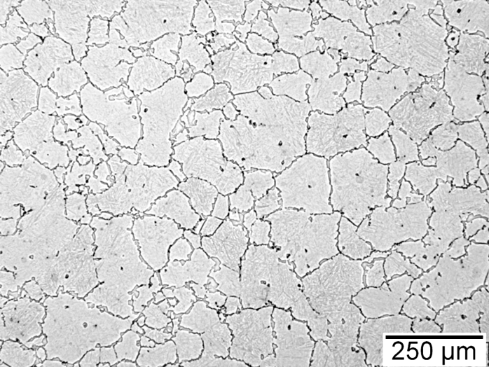
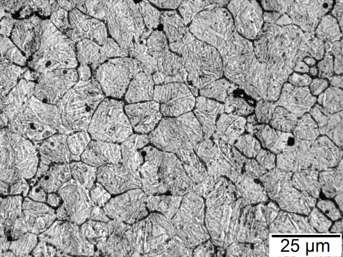
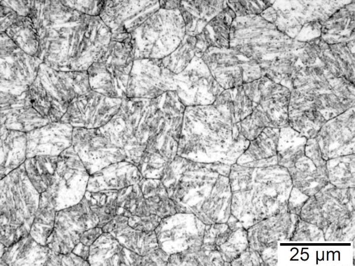
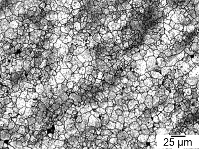
Figures 1-4 show examples of some of the more widely used techniques. FIgure 1 shows a specimen of modified 15V41 that was forced-air cooled from forging temperature, held for 30 minutes at 700°C, then quenched to room temperature and etched using 2 percent nital. Figures 2-4 represent examples of specimens that underwent no special heat treatment but use an etchant similar to Brownrigg et al. [7] to reveal the austenite grain size. Figure 2 shows the case region of an induction hardened 10V45 shaft. Figure 3 shows the core of a furnace-austenitized and quenched-modified 8620 specimen. Figure 4 shows an isothermally transformed bainitic modified 52100 specimen.
Selective Etching Techniques
Selective etching techniques such as the Bechet-Beaujard method [2] and its variants [7, 8] as well as a variety of other etchants [9-11] have distinct benefits over all other techniques. These etchants allow through hardened (both martensitic or bainitic) specimens to be examined with no additional heat-treatment steps that can bias the true austenite grain size of the process. However, achieving results that can be easily interpreted is far from a trivial task. Often each alloy and heat treatment requires a slightly modified methodology.
Example Etchant and Guidelines
The simplest austenite grain size etchant is water-based saturated picric acid solution but slight variations in the etchant, sample preparation, and methodology can dramatically improve results. It is believed that this etchant attacks trace elements such as phosphorus (P) that segregate to austenite grain boundaries at austenitizing temperatures. Therefore, special temper embrittlement heat treatments have been shown to improve etching results in alloys with low P content [8]. One instance in which this step is necessary is laboratory heats of steel that have very low P content. Another factor that is often overlooked is the specimen polish. A freshly polished metallographic specimen (1μm or finer) provides the best results. Below are an etchant and general procedure as well as a list of considerations developed from a review of the literature [7-11] that will provide a starting point for developing a procedure that will work for your process.
Etchant:
- 13 g/L picric acid in deionized (DI) water
- This is slightly above the solubility limit to ensure the solution is saturated.
- 3% Teepol
- Wetting agent. Substitutions can be made depending on availability of Teepol.
- Increasing the concentration for lower carbon levels (i.e. 0.2 wt.% C) has been shown to improve results.
- 1% hydrochloric acid
- Exact concentration depends on alloy. Sometimes this addition is not needed.
Procedure:
- Heat etchant to 65°C while stirring with magnetic stirrer. Keep etchant covered while not in use to prolong life.
- Each batch of etchant typically only lasts 2-3 specimens.
- Temperature can be reduced if etchant is observed to be too aggressive.
- Immerse specimen in etchant for 5-10 seconds. Specimen will tarnish significantly.
- Preheating the specimen on the hot plate or with a heat gun improves results.
- Rinse with DI water followed by ethanol.
- Lightly polish specimen by hand on a stationary medium- to high-nap polishing cloth with 1μm or finer diamond compound.
- Counting the number of revolutions around the pad helps repeatability. Less than 10 revolutions are typically all that is necessary.
- Clean with ethanol and dry with clean compressed gas.
- Inspect with light microscope.
- Try dark-field illumination to reveal the grain boundaries if bright-field produces marginal results.
- Repeat steps 2-6 until acceptable results are achieved.
References
- Standard Test Method for Determining Average Grain Size, ASTM E112-13, ASTM International, Oct. 2013.
- Steels – Micrographic Determination of the Apparent Grain Size, ISO 643:2003, International Organization for Standardization, 2003.
- Cayron, C., B. Artaud, and L. Briottet. “Reconstruction of Parent Grains from EBSD Data.” Materials Characterization, vol. 57. no. 4, 2006, pp. 386-401.
- L.M. Rothleutner, “Influence of Reheat Temperature and Holding Time on the Interaction of V, Al, and N in Air-cooled Forging Steels,” Thesis, Colorado School of Mines, 2012.
- L.M. Rothleutner, “Assessment of the Microstructure and Torsional Fatigue Performance of an Induction Hardened Vanadium Microalloyed Medium-carbon Steel,” Diss., Colorado School of Mines, 2016.
- M. Jiang, private communication, June 5, 2017.
- A. Brownrigg, P. Curcio, and R. Boelen, “Etching of Prior Austenite Grain Boundaries in Martensite,” Metallography, no. 8, 1975, pp. 529-533.
- D.R. Barraclough, “Etching of Prior Austenite Grain Boundaries in Martensite,” Metallography, no. 6, 1973, pp. 465-472.
- R. Riedl, “The Determination of Austenite Grain Size in Ferrous Metals,” Metallography, no. 14, 1973, pp. 119-128.
- G.F. Vander Voort, Metallography Principles and Practice, ASM International, Materials Park, OH, 1999, pp. 219-223.
- G. Petzow, Metallographic Etching, 2nd Edition, ASM International, Materials Park, OH, 1999, pp. 98-99.


 general practice for CQI-9 and AMS2750E")


