


Tempering hardened steels is one of the most important heat treating processes used in part manufacturing. Induction tempering produces hardness and mechanical properties similar to those produced using conventional oven tempering. The advancement of cell manufacturing led the way to combining induction hardening and tempering in the same manufacturing cell where other manufacturing operations are carried out, such as steel cutting, grinding, machining, and drilling. Thus, parts are completely manufactured including heat treating in the cell, one piece at a time. This lends itself to lean manufacturing. Hardening and tempering time cycles are of a much shorter duration than other processes in the cell. Optical pyrometers are often used to measure part surface temperatures achieved during hardening and tempering and are stored in a computer for use in statistical process control (SPC) calculations.
Tempering methods
There are five methods of induction tempering: single shot, continuous progressive, vertical scanning, conveyor, and slack quenching.
Single shot, or static heating, for tempering is best used for short parts or where a narrow zone must be tempered. This method uses separate power supplies and coils for both the hardening and tempering process. The workpiece must be allowed to completely cool to a temperature below 150°F before starting the tempering cycle.
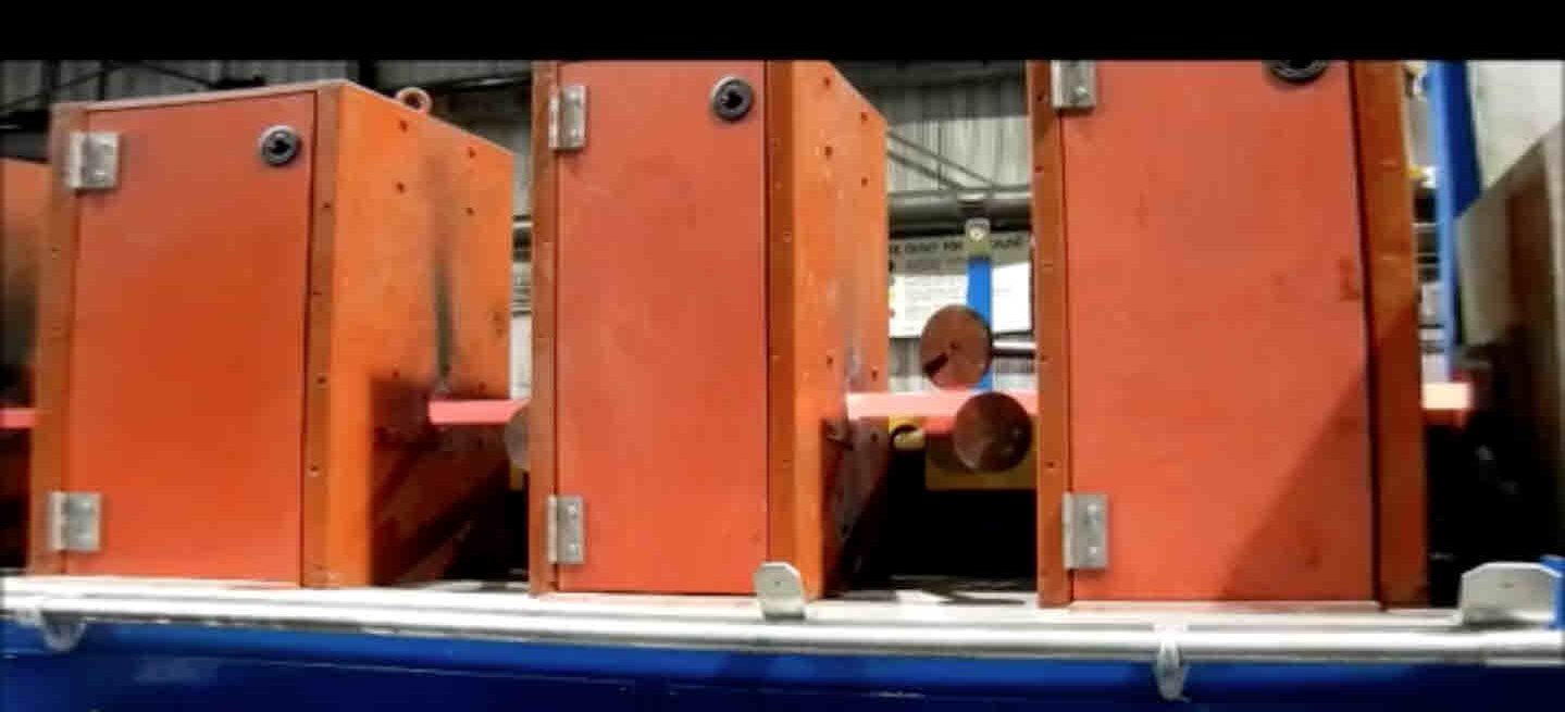
Continuous progressive is used to process quenched and tempered bar and pipe (see Image 1). Parts 8 to 24 feet long are commonly processed end to end. These induction systems are common in large production shops. In the process, a bundle of unhardened bars, pipe, or tubes is indexed to a positive drive, and individual pieces pass through a series of induction coils at a controlled forward rate. The pieces are slightly rotated while moving through the coils until they reach the austenitizing temperature (approximately 1,700°F) and then pass through a series of quenching chambers for cooling. Following cooling, they pass through a series of lower power, lower frequency induction coils at the same forward motion rate. After heating for tempering, the workpieces are indexed to a slow cooling table and then to final bundling. Advanced computer controls combined with optical pyrometers enable a repeatable process, as all process recipes and control limits are stored in the computer for each material type and diameter.
Vertical scanning is commonly used to induction harden the workpiece in one pass. A second scan is then used for induction tempering after the workpiece temperature stabilizes below 150°F. The quench is not turned on during the temper cycle to allow heat to penetrate deeper than in the original hardening cycle. The second pass for tempering uses only about 30 percent of the power used for hardening and a slower (30-50 percent) scan speed than that for hardening.
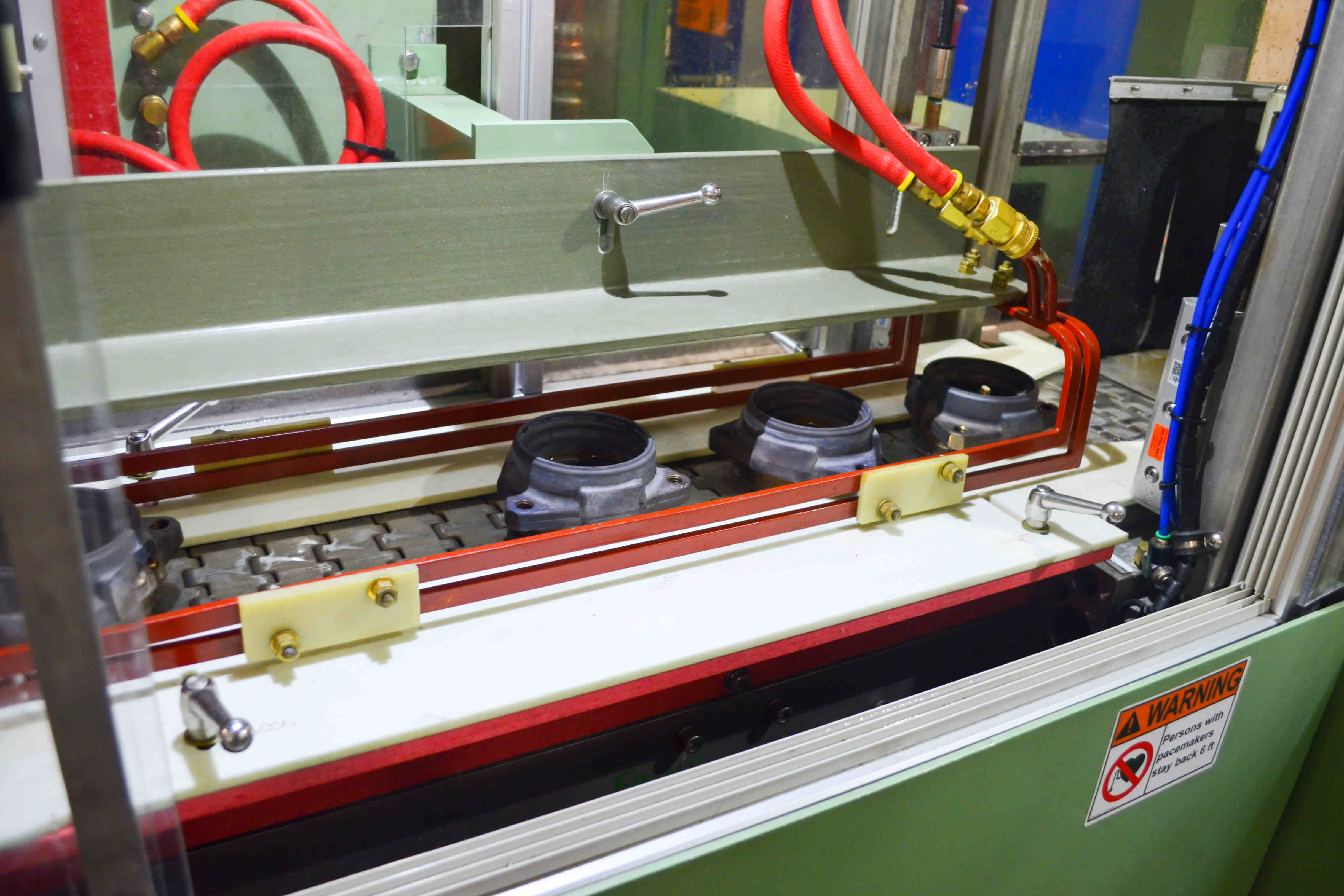
Conveyor tempering uses a channel-type coil with very low power densities over an extended period of time (see Image 2). The coil uses a separate power supply and lower frequency than used for hardening. After the part is hardened and part temperature has equalized to the quench media temperature, the part enters onto a conveyor at a controlled rate of forward motion and is reheated to the required tempering temperature. Usually more than one part is being heated at the same time on the conveyor in a hairpin or channel coil with power left on continuously. The low power density enables the temperature to equalize throughout the workpiece via conduction.
Slack quenching (leaving residual heat from the hardening process in the workpiece) is used regularly in large-diameter single shot and with horizontal scanners. In single shot hardening on large parts, there is a significant amount of heat in the part. The spray quench volume and time is controlled to produce a completely transformed microstructure at which point quenching stops and allows subcase heat to migrate back to the hardened case to reduce stress and hardness.
For example, SAE 1045 carbon steel cylinder rods are induction hardened using a horizontal scanner. Typical case depths are 1.5 to 2.5 mm. The forward motion of the rod through the quench at up to 3 inches per second enables controlling the exit temperature of the bar in the 350°F range to reduce as-quenched hardness from 64 to 60 HRC. This method uses the residual heat and no further tempering is required. Tight control of quench temperature, quench pressure, and quench flow is managed through a computer and PLC. The larger the diameter, the easier it is to control the exit temperature. It is harder to control smaller diameter bars because they have less total residual heat and, therefore, a smaller process window.


 general practice for CQI-9 and AMS2750E")


