


An infrared thermometer measures temperature by detecting the infrared energy emitted by all materials at temperatures above absolute zero, (zero degrees Kelvin). The most basic design consists of a lens to focus the infrared (IR) energy onto a detector, which converts the energy to an electrical signal that can be displayed in units of temperature after being compensated for ambient temperature variation. This configuration facilitates temperature measurement from a distance without contact with the object to be measured.
As such, the infrared thermometer is useful for measuring temperature under circumstances where thermocouples or other probe-type sensors cannot be used or do not produce accurate data for a variety of reasons. Some typical circumstances are where the object to be measured is moving; where the object is surrounded by an EM field, as in induction heating; where the object is contained in a vacuum or other controlled atmosphere; or in applications where a fast response is required.
Designs for an infrared thermometer (IRT) have existed since the late 19th century, and various concepts were featured by Charles A. Darling [1] in his 1911 book “Pyrometry.” However, it was not until the 1930s that the technology was available to turn these concepts into practical measuring instruments. Since that time, there has been considerable evolution in the design, and a large amount of measurement and application expertise has accrued. At the present time, the technique is well-accepted and is widely used in the industry and in research.
Measurement Principles
As previously stated, IR energy is emitted by all materials above zero degrees K. Infrared radiation is part of the electromagnetic spectrum and occupies frequencies between visible light and radio waves. The IR part of the spectrum spans wavelengths from 0.7 micrometers to 1,000 micrometers (microns). See Figure 1. Within this wave band, only frequencies of 0.7 microns to 20 microns are used for practical, everyday temperature measurement. This is because the IR detectors available to the industry are not sensitive enough to detect the small amounts of energy available at wavelengths beyond 20 microns.

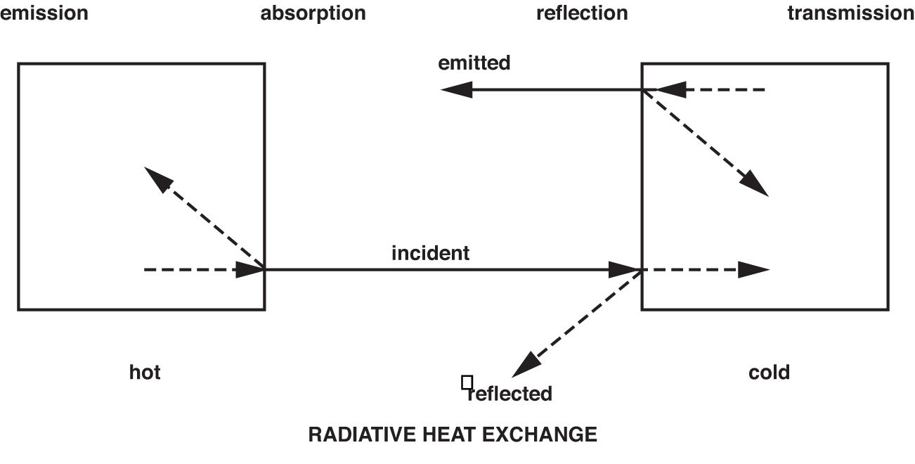
Though IR radiation is not visible to the human eye, it is helpful to imagine it as being visible when dealing with the principles of measurement and when considering applications. Because, in many respects, it behaves the same way as visible light. IR energy travels in straight lines from the source and can be reflected and absorbed by material surfaces in its path. In the case of most solid objects opaque to the human eye, part of the IR energy striking the object’s surface will be absorbed, and part will be reflected. Of the energy absorbed by the object, a proportion will be re-emitted, and part will be reflected internally. This will also apply to materials transparent to the eye, such as glass, gases, and thin, clear plastics. But in addition, some of the IR energy also will pass through the object (illustrated in Figure 2). These phenomena collectively contribute to what is referred to as the emissivity of the object or material.
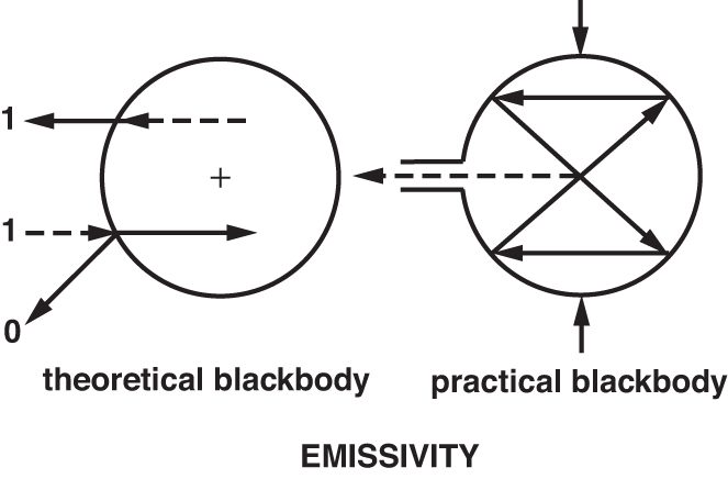
Materials that do not reflect or transmit any IR energy are known as blackbodies and are not known to exist naturally. However, for the purpose of theoretical calculation, a true blackbody is given a value of 1.0. The closest approximation to a blackbody emissivity of 1.0, which can be achieved in real life, is an IR opaque, spherical cavity with a small tubular entry (see Figure 3). The inner surface of such a sphere will have an emissivity of 0.998.
Different kinds of materials and gases have different emissivities and will emit IR at different intensities for a given temperature. The emissivity of a material or gas is a function of its molecular structure and surface characteristics. It is not generally a function of color unless the source of the color is a radically different substance to the main body of material. A practical example of this is metallic paints with significant amounts of aluminum. Most paints have the same emissivity irrespective of color, but aluminum has a different emissivity that will modify the emissivity of metallized paints.
Just as is the case with visible light, the more highly polished some surfaces are, the more IR energy the surface will reflect. Therefore, the surface characteristics of a material also will influence its emissivity. In temperature measurement, this is most significant in the case of infrared opaque materials with an inherently low emissivity. Thus, a highly polished piece of stainless steel will have a much lower emissivity than the same piece with a rough, machined surface. This is because the grooves created by the machining prevent much of the IR energy from being reflected. In addition to molecular structure and surface condition, a third factor affecting the apparent emissivity of a material or gas is the wavelength sensitivity of the sensor, known as the sensor’s spectral response. As stated earlier, only IR wavelengths between 0.7 microns and 20 microns are used for practical temperature measurement. Within this overall band, individual sensors may operate in only a narrow part of the band, such as 0.78 to 1.06, or 4.8 to 5.2 microns. These reasons will be explained later.
Theoretical Basis for IR Temperature Measurement
The formulas that infrared temperature measurement is based on are old, established, and well-proven. It is unlikely most IRT users will need to make use of the formulas, but knowledge of them will provide an appreciation of the interdependency of certain variables and serve to clarify the aforementioned. The important formulas include:
- Kirchoff’s Law: When an object is at thermal equilibrium, the amount of absorption will equal the amount of emission.
- Stephan Boltzmann Law: The hotter an object becomes, the more infrared energy it emits.
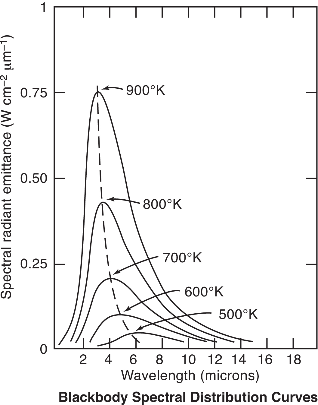
- Wien’s Displacement Law: The wavelength at which the maximum amount of energy is emitted becomes shorter as the temperature increases.
- Planck’s Equation: Describes the relationship between spectral emissivity, temperature, and radiant energy.
Infrared Thermometer Design and Construction
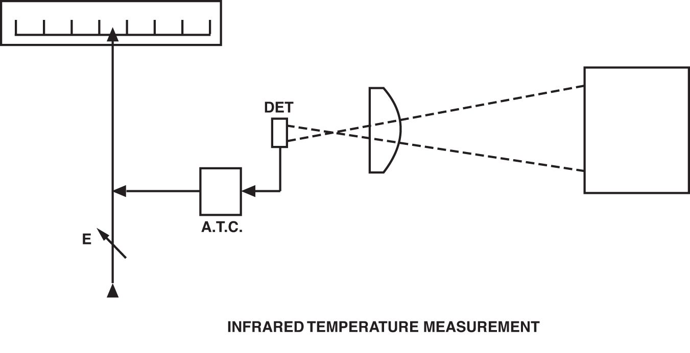
A basic infrared thermometer (IRT) design is comprised of a lens to collect the energy emitted by the target; a detector to convert the energy to an electrical signal; an emissivity adjustment to match the IRT calibration to the emitting characteristics of the object being measured; and an ambient temperature compensation circuit to ensure temperature variations within the IRT, due to ambient changes, are not transferred to the final output.
For many years, the majority of commercially available IRTs followed this concept. They were extremely limited in application and, in retrospect, did not measure satisfactorily in most circumstances, though they were durable and adequate for the standards of the time (see concept illustrated in Figure 4).
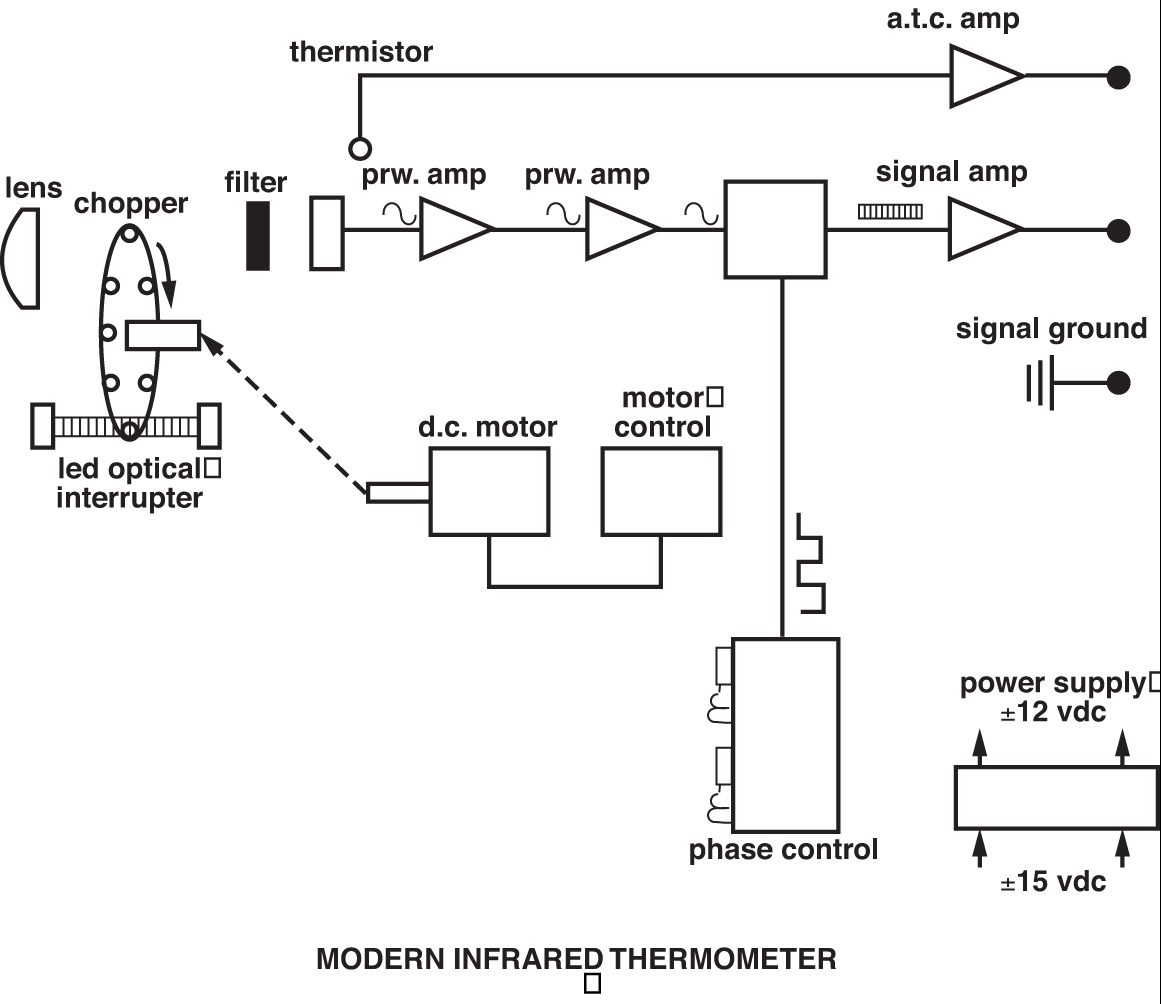
The modern IRT is founded on this concept, but it is more technologically sophisticated to widen the scope of its application. The major differences are found in the use of a greater variety of detectors; selective filtering of the IR signal; linearization and amplification of the detector output; and provision of standard, final outputs such as 4-20 mA, 0-10 Vdc, etc. Figure 5 shows a schematic representation of a typical contemporary IRT. Probably the most important advance in infrared thermometry has been the introduction of selective filtering of the incoming IR signal — made possible by the availability of more sensitive detectors and more stable signal amplifiers. Whereas the early IRTs required a broad spectral band of IR to obtain a workable detector output, modern IRTs routinely have spectral responses of only 1 micron. The need to have selected and narrow spectral responses arises because it is often necessary to either see through some form of atmospheric or other interference in the sight path or to obtain a measurement of a gas or other substance that is transparent to a broad band of IR energy.
Some common examples of selective spectral responses are 8-14 microns, which avoids interference from atmospheric moisture over long path measurements; 7.9 microns, which is used for the measurement of some thin film plastics; and 3.86 microns, which avoids interference from CO2 and H2O vapor in flames and combustion gases. The choice between a shorter or longer wavelength spectral response also is dictated by the temperature range because, as Planck’s Equation shows, the peak energy shifts toward shorter wavelengths as the temperature increases. The graph in Figure 6 illustrates this phenomenon. Applications that do not demand selective filtering for the previously stated reasons often may benefit from a narrow spectral response as close to 0.7 microns as possible. This is because the effective emissivity of a material is highest at shorter wavelengths and the accuracy of sensors with narrow spectral responses is less affected by changes in target surface emissivity.
It will be apparent from the foregoing information that emissivity is an important factor in infrared temperature measurement. Unless the emissivity of the material being measured is known and incorporated into the measurement, it is unlikely that accurate data will be obtained. There are two methods for obtaining the emissivity of a material:
- Referring to published tables.
- Comparing the IRT measurement with a simultaneous measurement obtained by a thermocouple or resistance thermometer, and adjusting the emissivity setting until the IRT reads the same.
Fortunately, the published data available from the IRT manufacturers and some research organizations is extensive, so it is seldom necessary to experiment. As a rule of thumb, most opaque, non-metallic materials have a high and stable emissivity in the 0.85 to 9.0 range, and most un-oxidized, metallic materials have a low to medium emissivity from 0.2 to 0.5, with the exception of gold, silver, and aluminum, which have emissivities in the order of 0.02 to 0.04 and are, as a result, difficult to measure with an IRT. While it is almost always possible to establish the emissivity of the basic material being measured, a complication arises in the case of materials that have emissivities that change with temperature, such as most metals, and other materials such as silicon and high-purity, single-crystal ceramics. Some applications that exhibit this phenomenon can be solved using the two-color ratio method.
Two-Color Ratio Thermometry
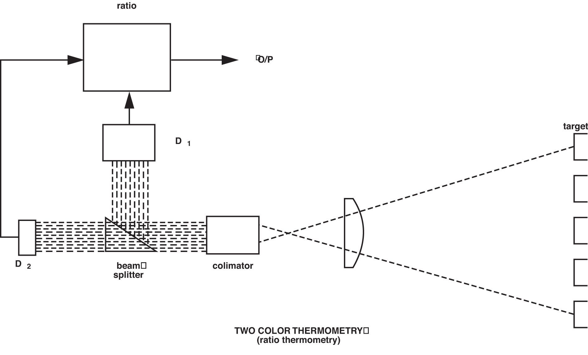
Given that emissivity plays such a vital role in obtaining accurate temperature data from infrared thermometers, it is not surprising that attempts have been made to design sensors that would measure independently of this variable. The best known and most commonly applied of these designs is the two-color ratio thermometer. This technique is not dissimilar to the infrared thermometers described so far, but it measures the ratio of infrared energy emitted from the material at two wavelengths, rather than the absolute energy at one wavelength or wave band. The use of the word “color” in this context is somewhat outdated, but nevertheless has not been superseded. It originates in the old practice of relating visible color to temperature, hence “color temperature.”
The basis for the effectiveness of two-color thermometry is that any changes in either the emitting property of the material surface being measured or in the sight path between the sensor and the material will be “seen” identically by the two detectors, and thus the ratio and therefore the sensor output will not change as a result. Figure 7 shows a schematic representation of a simplified two-color thermometer.
Because the ratio method will, under prescribed circumstances, avoid inaccuracies resulting from changing or unknown emissivity, obscuration in the sight path, and the measurement of objects that do not fill the field of view, it is useful for solving some difficult application problems. Among these are the rapid induction heating of metals, cement kiln burning zone temperature, and measurements through windows that become progressively obscured, such as vacuum melting of metals. It should be noted, however, that these dynamic changes must be “seen” identically by the sensor at the two wavelengths used for the ratio, and this is not always the case. The emissivity of all materials does not change equally at two different wavelengths. Those materials that do are called “greybodies.” The ones that do not are called “non-greybodies.” Not all forms of sight-path obscuration attenuate the ratio wavelengths equally either. The predominance of particulates in the sight path that are the same micron size as one of the wavelengths being used will obviously unbalance the ratio.
Phenomena that are non-dynamic in nature, such as “non-greybody” material, can be dealt with by biasing the ratio — an adjustment referred to as “slope.” However, the appropriate slope setting must generally be arrived at experimentally. Despite these limitations, the ratio method works well in a number of well-established applications, and in others, is the best, if not the most preferred, solution.
Conclusion
Infrared thermometry is a mature but dynamic technology that has gained the respect of many industries and institutions. It is an indispensable technique for many temperature measurement applications and the preferred method for some others. When the user adequately understands the technology and all the relevant application parameters are properly considered, a successful application will usually result, providing the equipment is carefully installed. Careful installation means ensuring the sensor is operated within its specified environmental limits and adequate measures are taken to keep the optics clean and free from obstructions. When choosing a manufacturer, a factor in the selection process should be the availability of protective and installation accessories and the extent in which these accessories allow rapid removal and replacement of the sensor for maintenance. If these guidelines are followed, the modern infrared thermometer will operate more reliably than thermocouples or resistance thermometers in many cases.
References
- Darling, Charles R.; “Pyrometry. A Practical Treatise on the Measurement of High Temperatures.” Published by E.&F.N. Spon Ltd. London. 1911.


 general practice for CQI-9 and AMS2750E")


