


No matter the configuration, single or multi-chamber vacuum, batch integral quench, continuous, or even pits — an item that all furnaces have in common regardless of their size, design, and material handling and, if defective, can have catastrophic consequences, is doors.
Doors are the weak link in any furnace system because while reducing heat loss and withstanding pressure, they must also seal tightly enough to eliminate the minutest leak and in some cases, all leaks. The problem with doors is they must open and close repeatedly without fault and therefore they often, or should, demand the most maintenance.
The following describes the characteristics of a few door concepts starting with the vacuum furnace.
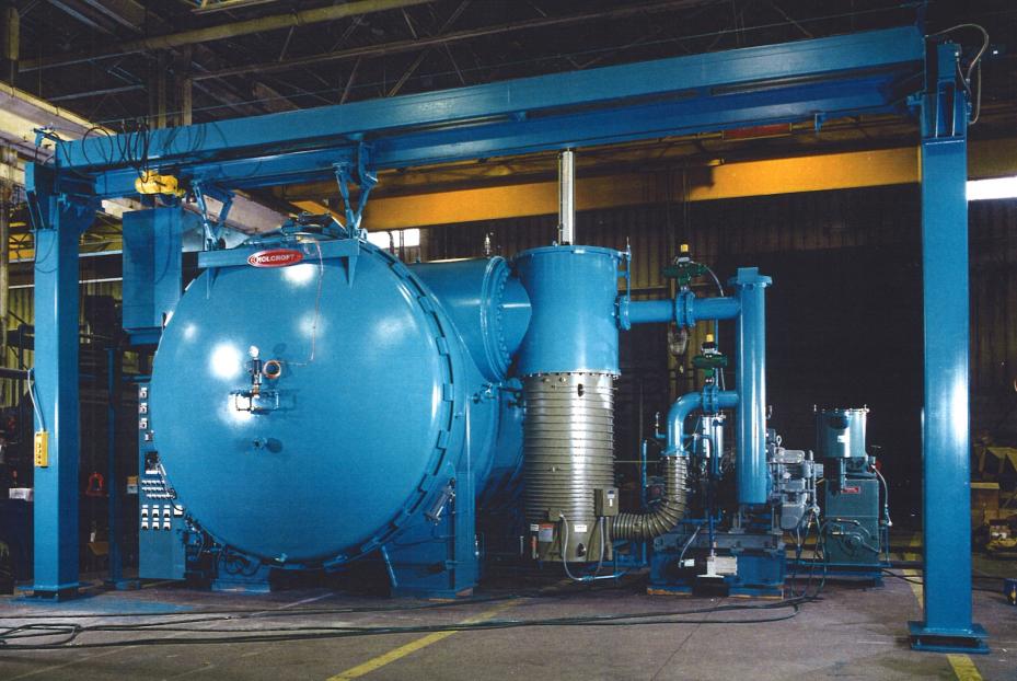
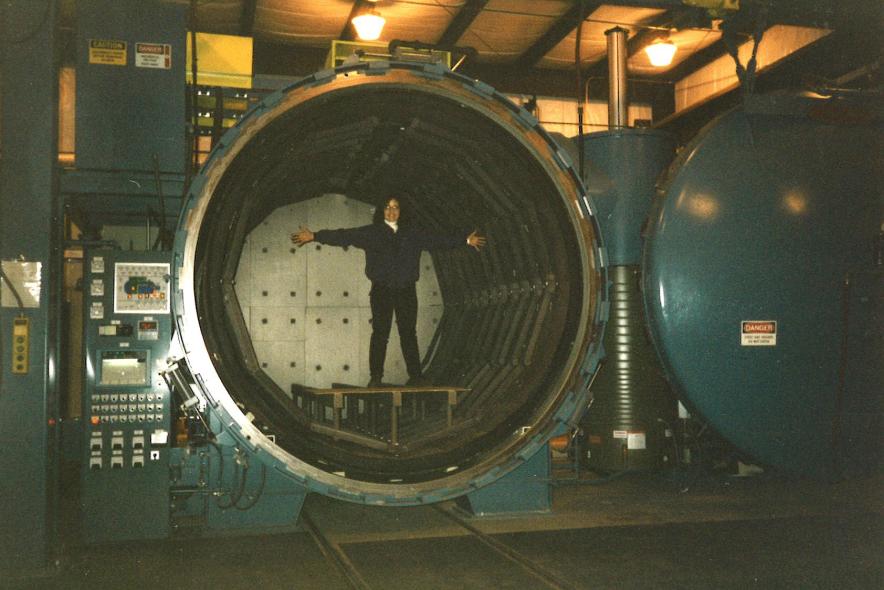
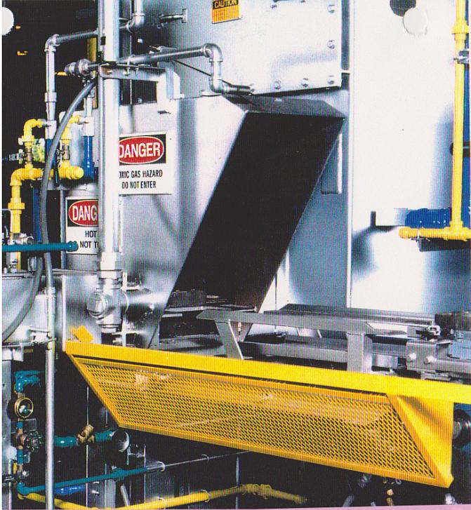
Elastomer seals such as o-rings are not absolutely leak tight. O-rings seal probably 99 percent of vacuum furnace doors and will leak perhaps only 7 x 10⁻⁷ cc/second (1.8 ft3/ month) at atmospheric pressure. Figure 1 and Figure 2 show a 10-foot-diameter 2-bar nitrogen or argon quench high-vacuum vessel that employs a suspended sliding charge door. This technique, instead of a swinging door, is used primarily to allow a track-mounted transfer car to pass in front of the vessel with the door open. A single o-ring provides the door seal with a rotating ring to hold the door closed. In addition, a carrier-mounted rollaway door closes the rear of the vessel for easier maintenance.
Batch integral quench (BIQ) carburizing furnaces use endothermic gas containing 40-percent hydrogen, 20-percent CO, and 40-percent nitrogen, so the integrity of its doors are just as or even more critical than vacuum furnaces. Carburizing takes place primarily between 1550°F and 1750°F (843°C and 954°C). BIQ furnaces usually have one position in the hot zone, vestibule, and quench tank with two doors — an inner door separating the quench vestibule from the hot zone and an outer vestibule door through which the tray is loaded onto an elevator above the quench oil. The inner door typically seals only around the perimeter with a designed leak at the bottom where the rear handler chain guide is located or centered in the door, continuously purging the vestibule with process gas. Although it’s obviously not gas-tight, the door is designed to provide a heat seal plus provide a defined gas flow path at a low point in the hot zone. Carburizing gas that is leaking over the top or sides of the inner door can make atmosphere control difficult. For the carburizing atmosphere to completely interact with the load, the hot zone must be constantly filled with gas and allow the recirculating fan to distribute the atmosphere through the parts. If the process gas is allowed to short-circuit around the door, it cannot dwell long enough in the hot zone to transport adequate carbon to the parts being carburized.
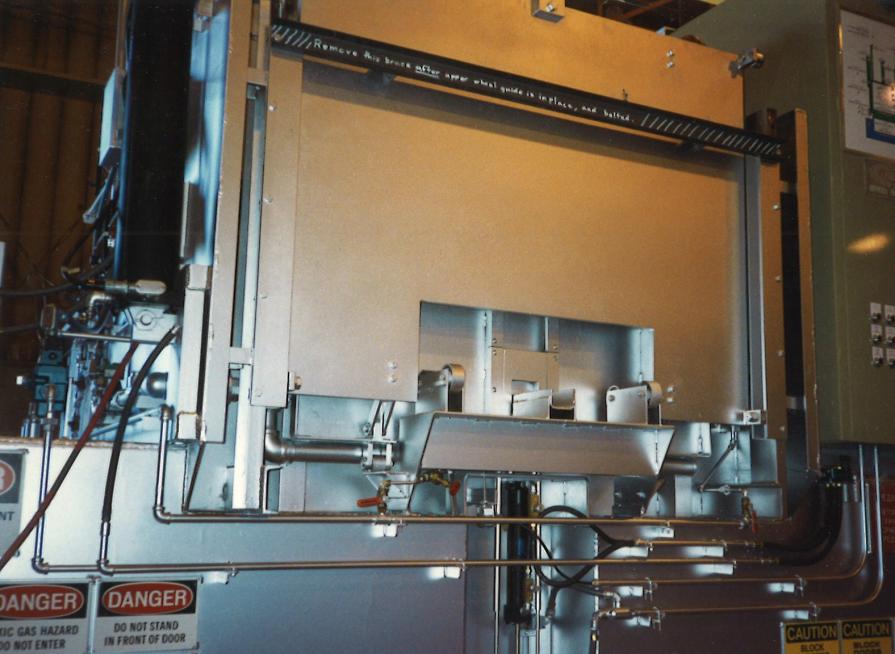
The Universal Batch Quench (UBQ) furnace’s outer or vestibule soft-sealed door not only plays a critical role by keeping air out, but also provides pressure relief (see Figure 3 and Figure 4). Many BIQ outer doors consist of a machined plate that slides open and closed via metal-to-metal contact against the vestibule frame.
No matter the furnace type — vacuum or atmosphere — carburizing has risks due to the hazardous nature of mixing atmospheres: acetylene/air for vacuum and hydrogen/air for endo gas. In BIQ furnaces, especially those with top-cool chambers, a premix of fuel and air could develop in the vestibule when the inner door is not timed properly. For example, if the inner door closes too quickly after transferring a tray to the vestibule for quenching, the vestibule atmosphere will cool and collapse rapidly, creating a partial vacuum and possibly pulling air into the confined space. As the carburizing atmosphere continues to purge the vestibule, the premix could ignite thus causing a significant gas expansion and increased pressure. This can be avoided by slowing the door’s descent thereby allowing the heated vestibule gas to cool more gradually and reducing the pressure deferential.
The force of the ignition is a direct function of how the vestibule door is sealed. The door shown in Figure 3 and Figure 4 allows the pressure from gas ignition to easily escape by overcoming the wedged weight that’s holding the door closed. An atmosphere seal is provided by the knife edge attached to the door, compressing a ceramic rope. After the internal pressure is released, the door again seals without damage.
Pusher furnaces have been and still are the high-production mainstay all over the world and may seem to define the mundane of heat treating equipment, but this is where the function of their doors is most critical to atmosphere control. Multi-zone and multi-row pusher furnaces have several doors of which only two — the charge and discharge doors — isolate the atmosphere from the plant environment. Inboard to both doors are at least two more doors that provide the heat seal and, like the BIQ inner door, have a leak point below the doors to allow atmosphere to escape through the push-across channel and purge the charge and discharge vestibules. Also like the BIQ furnace’s vestibule, the pusher charge and discharge vestibules have effluent pipes that provide the atmosphere exit point. Door sequencing occurs as such:
- One tray in the programmed selected row is pushed to the discharge push-across tunnel.
- The tray is pushed or pulled through the discharge tunnel through the discharge inner door into the quench vestibule.
- The tray is lowered into the oil and quenched.
- The quench vestibule is purged with endo gas.
- The outer charge door opens to push a new tray into the charge vestibule.
- The charge vestibule is purged with endo gas.
- The tray is pushed or pulled through the inner charge door into the charge tunnel.
- The tray is pushed into the row that discharged the previous tray.
- After quenching, the discharge door opens to remove the tray.
- All doors are closed.
This described sequence causes the atmosphere to move to the end of the furnace that has the path of least resistance. Thus, the quantity and composition of the atmosphere entering each zone must be compatible with the overall furnace carburizing potential, meaning that cold trays entering zone one must not cause the atmosphere to be compromised in zone two, three, etc.
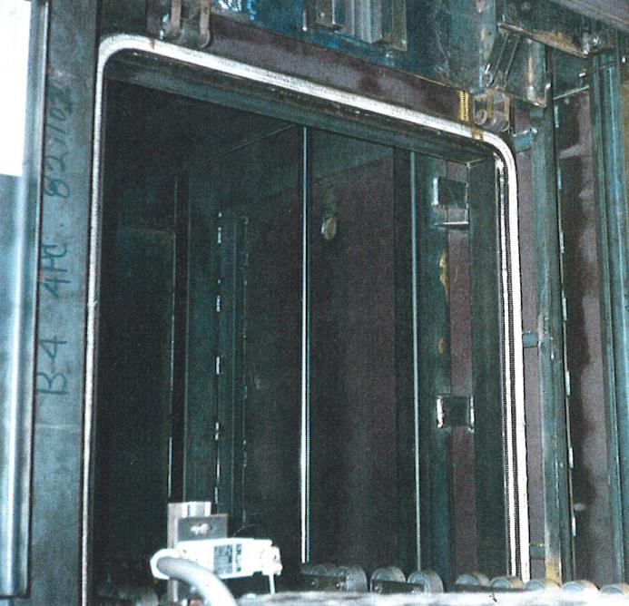
For this discussion, it’s noteworthy to mention two well-known doors used in heat treating today — one old, the Holcroft Pusher “alligator door” (shown in Figure 5), and one new, the AFC-Holcroft EZ™ Endo generator maintenance door (shown in Figure 6). As previously mentioned, the Achilles heel of any door is the constant opening and closing, causing wear and tear to sliding mechanisms and sealing membranes. But the alligator door has neither. As its name suggests, the door hinges at the bottom, integrating the tray skid rails inside of the door with a pneumatic cylinder, rotating the assembly up to closure, and eliminating any chance of abrasion to the ceramic rope seal membrane.
The second door is the first of its kind for an endothermic generator. All endo generators prior to the EZ™ system required the catalyst containing retort to be vertically lifted out of the heated case for maintenance, thus requiring excess overhead space. A typical 3,000 CFH (85 M3) retort will be approximately 9 feet (2,743 mm) long, which requires about 10 feet below the crane hook over the generator to remove the retort. A 4,500 CFH (127 M3) EZ™ generator provides a hinged door allowing the 9-foot-long retort to be removed horizontally via forklift or walk-behind loader. The side swinging door allows the user to locate the EZ™ generator anywhere in their plant where only 14 feet (4,267 mm) is required.


 general practice for CQI-9 and AMS2750E")


")

