


Ninety-eight 600-pound trays are in continuous process, 13 are in the pre-process queue, nine preheating, 14 in the boost carb, eight in the diffusion chamber, eight in equalize, three trays in one of three quench options, slow-cool, dunk-oil quench, and in the holding chamber for multiple stations in press quench. The remaining 43 trays are in various stages of wash, temper, material handling, and load/unload stations.
Each of the 98 trays can have a different case depth and cooling and/or quench recipe. Sound like a sophisticated lights-out, just-in-time heat-treating system? Absolutely, it’s a 21st century state-of-the-art hardening cell where the complexity of logic to control timing and tray tracking is nothing short of remarkable.
State-of-the-art certainly describes this heat-treating system, but even more significant is the cell that I will describe in the following column was sold 31 years ago, designed and commissioned in 1988.
At that time no one knew what a laptop was; iPhones, iPads, and android devices didn’t exist. In fact, early cellphones, if you could afford one, were the size of a loaf of bread. The National Science Foundation Network (NSFNET), the beginning of the internet, was known only to scientists, the government, and hardcore techies. And the price of gasoline was 93 cents a gallon.
In 1986, a world-class off-road and mining equipment manufacturer approached Holcroft, Inc. about building a state-of-the art heat-treat system that would allow them to machine and heat-treat parts to meet its 24-hour ship-anywhere-in-the-world guarantee.
The resulting carburizing and hardening system was designed to process gears and shafts fixtured on 30-inch square (762 mm), 600-pound gross loaded trays every 15 minutes. Flexibility was paramount with a minimum ECD (effect case depth) of 0.026 inches at 0.40 percent carbon. Maximum case depth could be any metric one was willing to wait for.
The triple rotary trademarked “ROTO – CARB™” consisted of a pusher preheat — three oil-sealed rotary carburizing furnaces, one feeding the other in a straight line arrangement with a wash, temper, and associated handling conveyors (Figure 1). All equipment occupied a footprint of about 102 feet (31 meters) x 69 feet, 6 inches (21.2 meters).
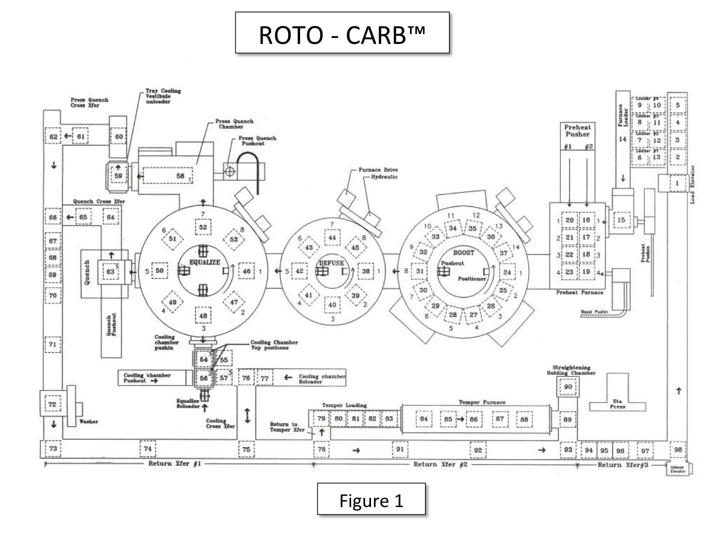
Four pre-positioned queues were available for trays with one position dedicated for urgent processing on a moment’s notice. Each tray was loaded with gears or shafts; the operator would queue in the ID and recipe, and they would be stored in the computer. Atmosphere control consisted of endo gas, but the custom oxygen probes were provided by the customer. Temperature set points were controlled by Baber Coleman 560 stand-alone instruments for all three rotary furnaces, preheat, temper, and holding chamber.
One of the control parameters critical to the operation was transferring trays between preheat, boost carb, diffuse, and equalize chambers. The rotaries continuously rotated and stopped only to transfer trays. However, before a tray could be transferred, an unoccupied space had to exist in the receiving location. This could only occur by continuously monitoring the location of each tray while knowing the time and case-depth requirement of every tray. Prior to loading a tray, an algorithm would test to determine if a space would be available in each of the furnace chambers to accommodate the boost carb, diffuse, and equalize recipe for the tray. If not, the next tray’s recipe in the queue would be interrogated and continue through the queue until a suitable load recipe was found. This process was controlled by then state-of-the-art computers — IBM AT units running the DOS operating system. There were two computers, one managing tasks in real time while the second AT was the hot backup. If the primary system went down, the backup would immediately take over without skipping a beat. Each computer had 20-megabyte hard drives, trivial capacity by today’s standards. In addition to the hard drives, each AT had dual 3.5-inch, 1.2 megabyte high-density floppy disk drives. Again, high end memory for the time. Discrete I/O, recipe management, and tray-handling motion was controlled via the same primary/backup philosophy as the computers but with Allen Bradley 2/30 PLCs. If the primary PLC failed, the backup would seamlessly take over.
(An interesting side note: the icon you click on in Windows to save a file is a replica of the 3.5-inch floppy disk.)
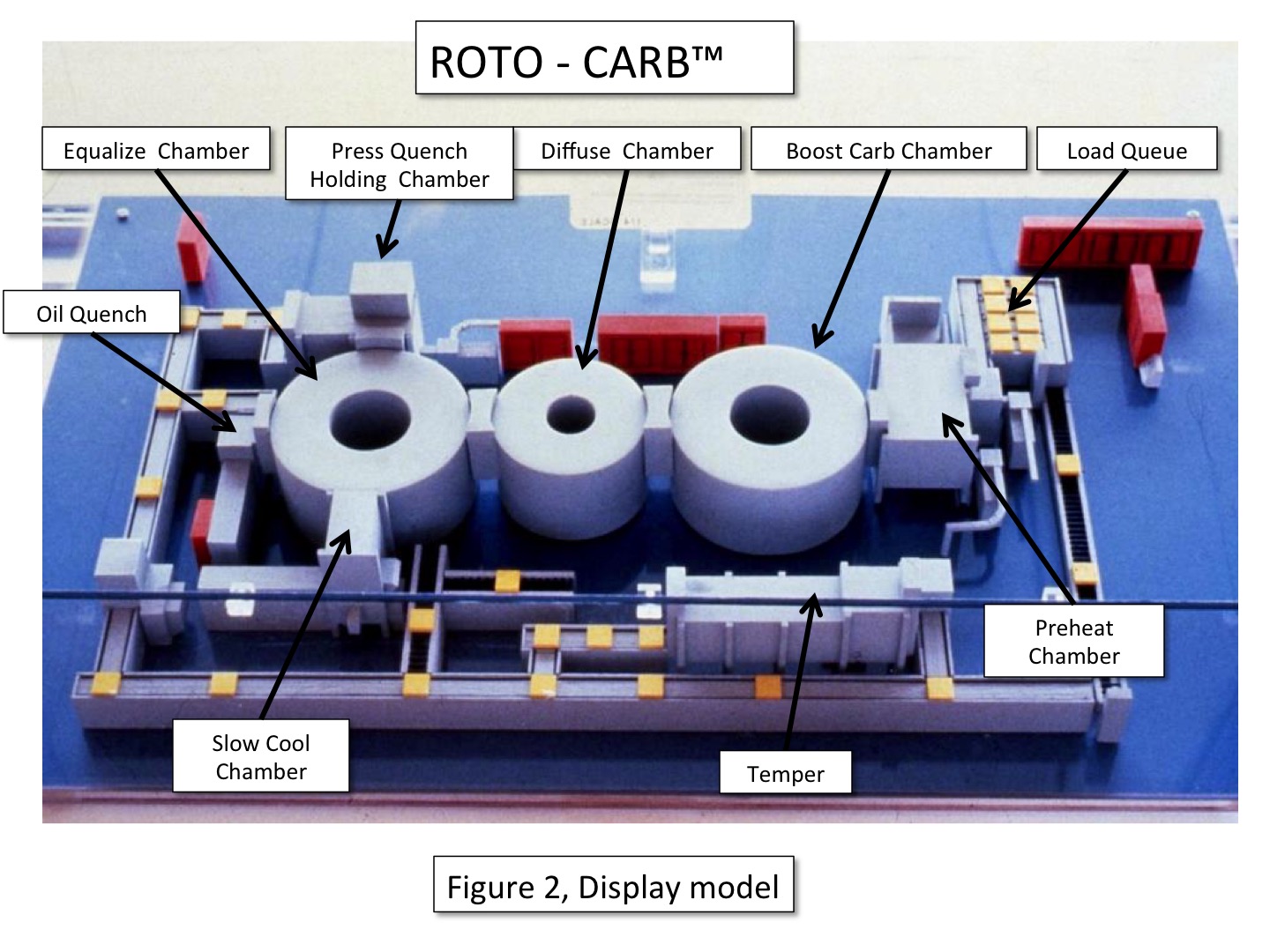
Trays would move from preheat into the boost carb rotary where the surface carbon would be increased to and maintained at approximately 1.10 percent to 1.30 percent, depending on the material and application. Likewise, the duration in the boost chamber would be monitored and, when the target case depth was achieved, moved to the diffuse chamber for the final near net-case depth while reducing the carbon potential to approximately 1.00 percent. The equalize rotary would receive a tray from the diffuse chamber and reduce the surface carbon to 0.85 percent to 0.90 percent while reducing the temperature to 1,550°F prior to quenching. Figure 2 is a display model of the ROTO – CARB™ cell.
Each rotary furnace had a maximum rotation speed of 1 rpm (revolution per minute). The minimum ECD mentioned above is based on the 15 minute Takt time and one-half revolution of the furnace. If the load mass was the appropriate value, less than 600 pounds, the recipe could produce shallower case depths by decreasing the time between trays entering the system.
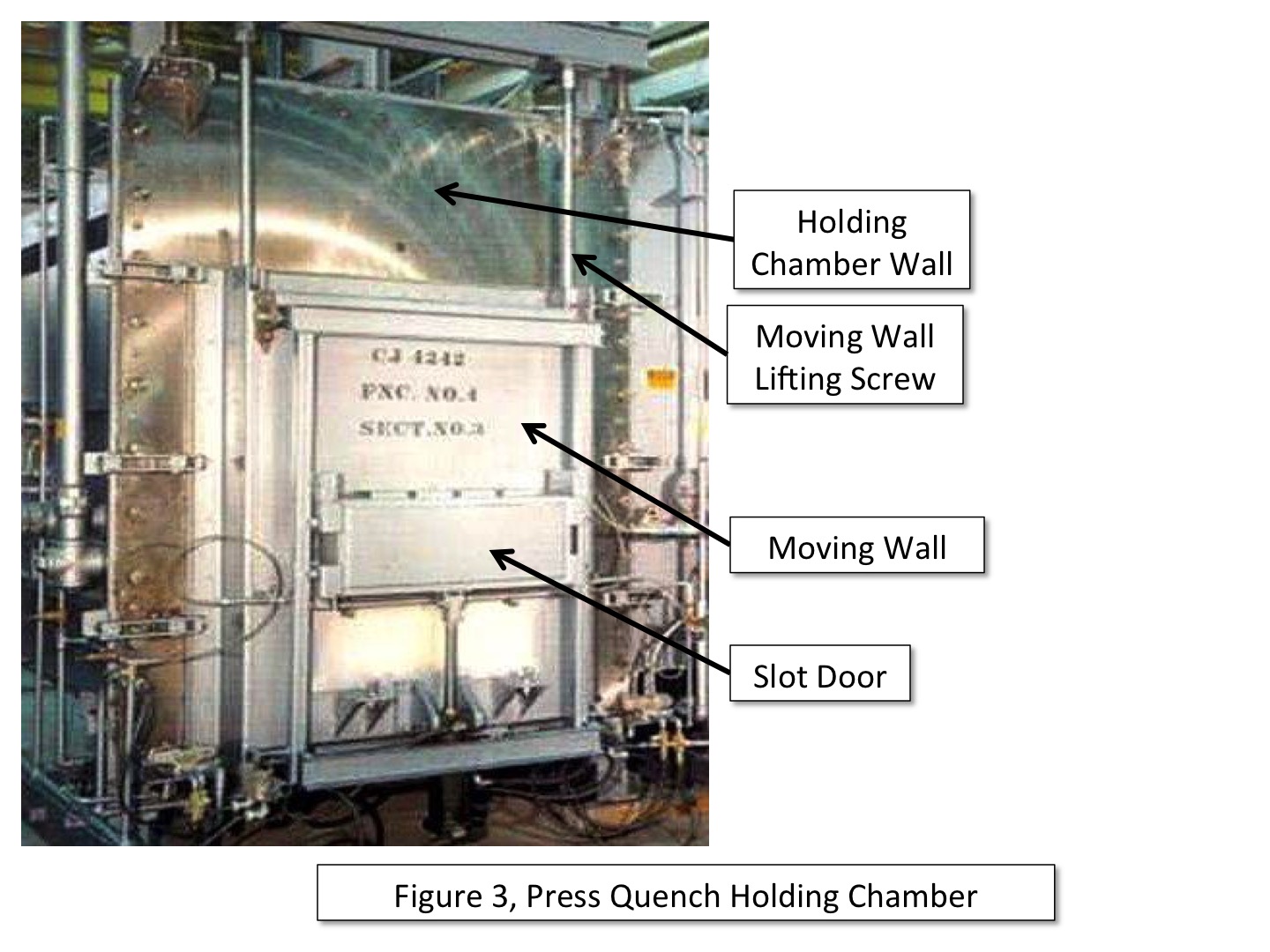
When the recipe called for a press quenching stacked or side-by-side gears, the tray would be diverted from the equalize rotary to the press quench holding chamber. In the chamber, two positions are available, one for removing stacked gears and the second for removing gears resting side-by-side. When stacked, the process logic would alert an operator of what was to come. If stacked, the operator would enable the slot door to open, and the tech would manually remove the top gear, then the spacer if used. The sliding wall would move lower to align the slot door with the next gear for removal. This sequence would continue until all stacked gears were press quenched. The empty tray, when instructed, would be moved to the tray cooling station where the quenched gears would be restacked on the cooled tray. When gears lie side-by-side, the tray would be positioned to the next holding chamber location where the wider slot door would allow the tech to remove both gears individually. To facilitate gear handling, a compressed air assisted manipulator helped the tech to move heavy gears to the press. Figure 3 is an example of the moving wall.
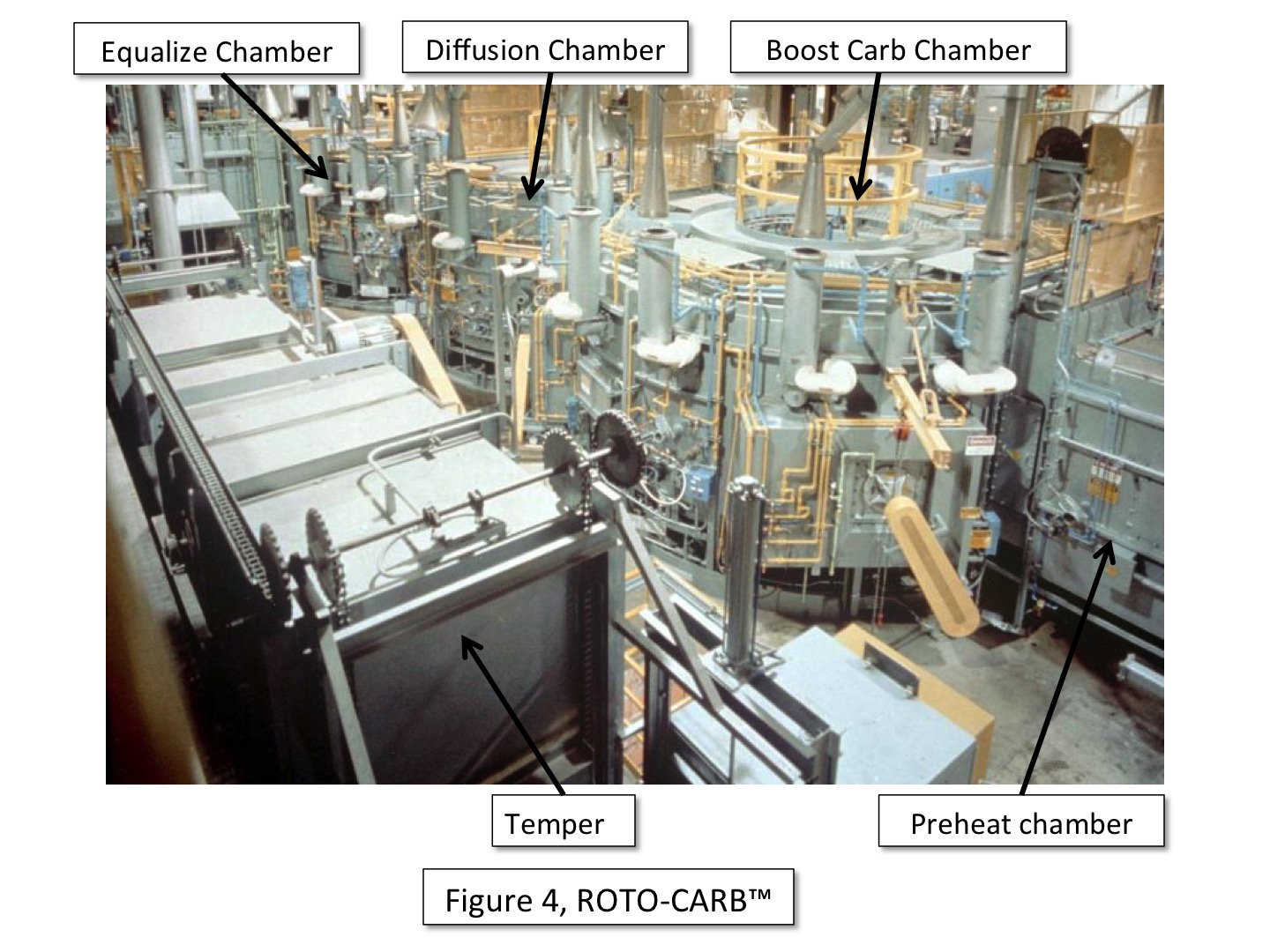
The second discharged position from the equalize chamber is the dunk-oil quench. This function operated much like a batch IQ furnace where the equalize push out would move a tray into the quench vestibule. The third cooling option consisted of one or two functions: The tray could be pushed out to the slow cooling chamber for complete cooling, or the tray could be cooled to <1,000°F (538°C) then recharged back into the equalize chamber for either dunk or press quenching. Figure 4 is a birds-eye view of the ROTO – CARB™ cell.
For those interested in PLC logic, the following is a partial explanation of the tray tracking logic used in the ROTO – CARB™ system, referencing Figure 1: When a tray was loaded at position 1, the information for the part/tray was moved to 1 of the 98 integer tracking files N1 to N98. All of the recipe data was loaded into that file. As the trays moved to a new position, the “pointer” (independent address in today’s PLC logic) for that position was modified to point at the storage integer file the previous position pointed at. For example, if data was loaded initially in N1, the data exists all the way through the system in N1, the position pointer was the only thing that changed. So for example, in position 9, whatever integer file the information for that part/tray was loaded into at position 1, that is the file position 9 pointer pointed at. When the tray moved to position 10, the pointer for position 10 would be updated with the file number that was in position 9, and then position 9 would be set to an empty file until a new tray was moved into it. Most of the time the entire data file just moved a pointer number that pointed to a fixed file. When a part/tray left the system, that integer file was freed up and put back in the open files to be used. After a while, files were not sequential because trays loaded later may be out before trays loaded first [1].
Ever since the term “lean manufacturing” entered our lexicon, reducing inventory in the manufacturing chain has been a primary goal. To manufacture an item meant parts required in making a product must arrive at the assembly station “just-in-time.” Heat treating, and carburizing in particular, where many parts are processed simultaneously could frustrate that effort. However, Holcroft Inc. had a solution to that conundrum: it’s called the rotary hearth carburizing furnace. In essence, flexibility is the key word here, flexibility to overcome the first-in-first-out obstacle many manufacturing processes endure.
Rotary furnaces can operate in two ways: They can function like a pusher turned into a circle where the trays follow the first-in-first-out scenario, one revolution and out, or like ROTO – CARB™ where they can dwell as long as desired to achieve the desired case depth or one-half revolution.
In my view, the rotary furnace has not been applied as often as it should for its just-in-time functionality and flexibility. In addition, rotary furnaces, regardless of type, are self-emptying, meaning that unlike pushers that require empty trays to push out full ones to change recipes, they satisfy the lean manufacturing philosophy. Rotary furnaces can be made in almost any size with as few as four trays of almost any size and integrated into a variety of cell and quench configurations.
Reference
- Logic explanation provided by Henry Baker, AFC-Holcroft.


 general practice for CQI-9 and AMS2750E")


