


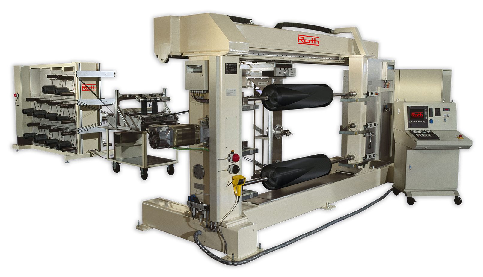
Filament winding is a manufacturing method for making tubular and cylindrical shapes of extreme strength and light weight. The technology involves wrapping a mandrel — which is a reusable steel core with resin-impregnated carbon fiber, Kevlar, or Fiberglas fiber — and then curing it in an oven. The mandrel is rotated while the fiber is kept taut during the wrapping process, and the fibers are pulled through a bath of liquid resin (epoxy, polyester, vinylester, or phenolic) before being wound onto the mandrel (Figure 1).
This process is used to produce water tanks, pressure tanks, pipes, missile housings, bicycle parts, golf clubs, aircraft components, power-transmission poles, filter housings, and many other parts used in industry, recreation, and the military. First used in 1968 for making Fiberglas reinforced pipe, the technology has been developed to manufacture tubular shapes with diameters from 10 to 158 inches.
After winding, the tubular shapes must be cured in an oven at 200° F to 400° F to harden the resin. The mandrels have to be kept rotating while being cured to nullify the effect of gravity on the resin and ensure a round profile. There are interesting ways this is done, and several oven configurations are used.
Load Cart With Rotator
In this method of curing wound mandrels, the mandrels are loaded onto a cart that carries them into a batch oven. The ends of the mandrels are left bare (no filaments wound on them) for handling purposes, and the load cart has rollers that support the mandrels in these areas at both ends (Figure 2).
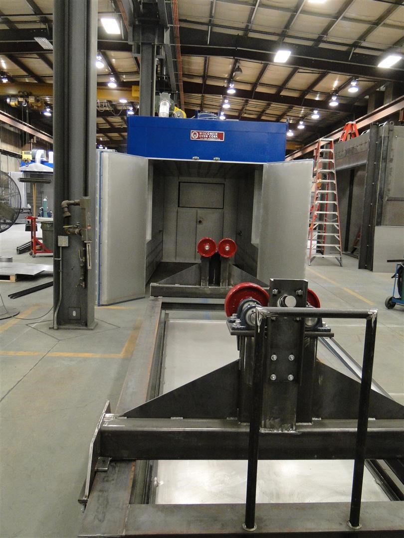
One of the rollers is powered to rotate the mandrels resting on them. They rotate slowly, just enough to keep the resin from migrating downward due to gravity. The rotation is achieved using a gear drive. In order to protect the drive system from heat damage, it is located outside the oven with a drive shaft (or shafts) protruding into the heating chamber through a seal. This is accomplished two ways: either with the drive system located on the cart, protected from the heat by an insulated plug; or with the drive located at the oven rear, outside the oven.
This system can handle mandrels up to 6,000 pounds, 5 feet in diameter, and 12 feet long, or even larger if required. The load cart design allows the wound mandrels to be loaded via overhead hoist. It is not unusual for an oven to cure multiple mandrels at one time and therefore have multiple rotators. There are two ways the cart drive rotates the mandrel without being exposed to the heat: the cart-mounted drive and the rear-mounted drive.
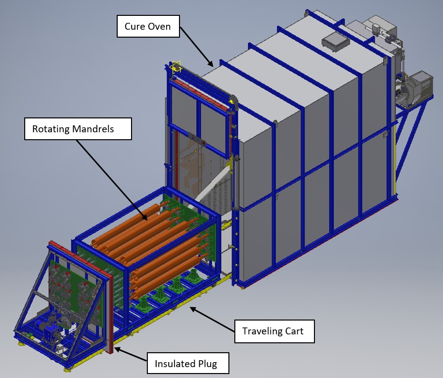
In the cart-mounted rotator drive design, the load cart has an insulated plug (essentially a heat barrier) that sits between the gear drive and the heating chamber. The plug is mounted to the cart (Figure 3), and travels with it as the cart moves. It is located at the rear of the cart, so that when the cart is in position inside the oven, the plug closes off the oven opening, serving as the oven door. When the cart is outside the oven, the plug is out of the way, permitting loading/unloading of the mandrels.
As the weight of the cart loaded with mandrels is typically too large to move manually, the entire cart is driven in and out of the oven mechanically. This requires a second drive to rotate the cart wheels (at least two of them), which moves the cart in and out of the oven. This drive is also located on the cart on the cold side of the plug. To bring power to the drives, a cord reel or power track is used. The advantage of the cart-mounted drive design is that the mandrels can be kept rotating while outside the oven, which is sometimes necessary.
The other style of rotator design is the rear-mounted drive arrangement. In this design, the gear drive that rotates the mandrels is located at the oven rear on the outside of the back wall of the oven (Figure 4), protected from the heat.
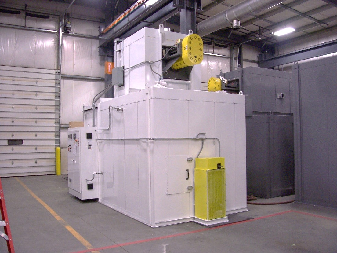
The gear drive rotates a shaft that penetrates through the oven rear wall. The end of the shaft inside the oven has a coupler mounted to it that engages a mating coupler on the rear of the cart and drives one of the mandrel support rollers on the cart. A key aspect of this design is that the coupler pair must be engineered so that, as the cart enters the oven, the two halves of the coupler automatically engage while the cart moves into place inside the oven, no matter what their rotational position.
Another key feature of the design is the heat seal where the drive shaft penetrates through the oven wall. The seal must allow rotation of the shaft without binding or excess friction, while preventing heat from escaping and damaging the gear drive. The rear mounted mandrel drive is less expensive than mounting the drive on the traveling load cart, but the disadvantage is that the mandrels cannot be rotating while the cart is outside the oven, since the drive is disengaged at that time. This is as opposed to the cart-mounted drive, which normally continues to rotate the mandrels even while the cart is outside the oven. It is sometimes necessary to keep the mandrels rotating at all times, even outside the oven, for example when there are multiple mandrels being carried on the cart at the same time. It may take 15 minutes or more to load multiple uncured mandrels onto the cart, which is long enough for gravity to affect the uncured resin if they are stationary.
Airflow Pattern
Cure ovens for fiber-wound composites can be electric or gas heated. The heat is often generated in a separate heater house, where the fan is located, then delivered to the heating chamber through supply ducts. The ducts have adjustable louvers to fine-tune the volume of air being delivered to different areas of the oven. As with many types of convection thermal processing, a higher volume of recirculated airflow provides the best temperature uniformity and oven performance.
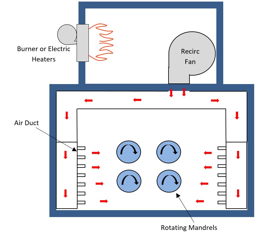
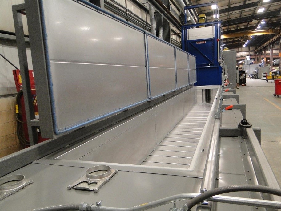
It is also important the supply ducts that deliver the air are located such that they thoroughly and evenly deliver the heated air to the mandrel. The air supply ducts are normally located on both sidewalls, near the floor of the oven (Figure 5), and extend all the way from the front to the rear of the heating chamber to evenly deliver the air. This arrangement is referred to as combination airflow, since the air travels both horizontally and vertically through the workspace. The exact volume of recirculated air required is calculated, and the blower that moves the air is sized accordingly. It is critical the oven be specifically engineered for curing wound mandrels. A general-use industrial oven may not provide good results in curing fiber-wound mandrels.
Post Cure of Filament-Wound Mandrels
Depending on the resin formulation and other details, the wound, cured mandrels sometimes undergo a secondary (a k a final) cure. They don’t need to be kept rotating during the final cure and can sometimes be heated while upright.
Top-Load Oven Design
Another popular oven design for curing filament-would mandrels is the top-load oven, sometimes referred to as a coffin oven (Figure 6).
In this design, the oven door is located on the top, and the wound mandrels are loaded into the oven via overhead hoist. The oven door is commonly opened using a chain-lift system, powered either electromechanically or pneumatically, mounted to the side of the oven. The door can also be manually operated in some cases. A counterweight can be used to reduce the lifting force required. Further, the door can be split into multiple sections, each of which are easier to lift than the entire door would be. As with the load-cart style oven mentioned earlier, there are roller-style supports inside the oven at both ends of the heating chamber. The ends of the mandrels rest on the rollers, which are rotated using a powered drive located outside the oven. The drive is coupled to a shaft penetrating the oven end.
The primary advantage of the top-load design is that it requires less floor space than a cart-style oven. The oven footprint only needs to accommodate the width and length of the part. This is in comparison to the cart style oven, the footprint of which must not only accommodate the oven, but also the cart while outside the oven. The top-load oven footprint is, therefore, roughly half of the cart-style oven. The supply ducts that deliver the heated air are most often located on both side walls, the same as in the cart style ovens, but can also be located at one end and direct the air axially down the length of the heating chamber, which is referred to as “end flow.”
Find the Right Partner
If you need to purchase or specify an oven for curing filament-wound composites, find a reputable oven manufacturer that can demonstrate experience and knowledge of both the curing process and effective handling and rotating of the wound mandrels. Look for a supplier that offers a 3-year or 5-year warranty at no additional charge. This shows they stand behind their product. A solid partnership with a good oven supplier will ensure your project is a success.


 general practice for CQI-9 and AMS2750E")


