


There are various types of high-efficiency gas burners and radiant tubes currently on the market, and economic tools can be used to assess investments in heating technology for industrial furnaces. In addition, a revolutionary combustion technology now makes it possible to have the best of both worlds — increased efficiency and suppressed NOx emissions.
Gas Burner Technology
The graph in Figure 1 shows combustion efficiency (based on the lower heating value) as a function of exhaust gas temperature prior to the heat exchanger (if one exists for a particular burner type). In the case of a direct-fired burner, this is equal to the temperature of the furnace. In the case of a radiant tube burner, this temperature is higher than the furnace temperature by an amount that is related to the heat flux density across the radiant tube [1].
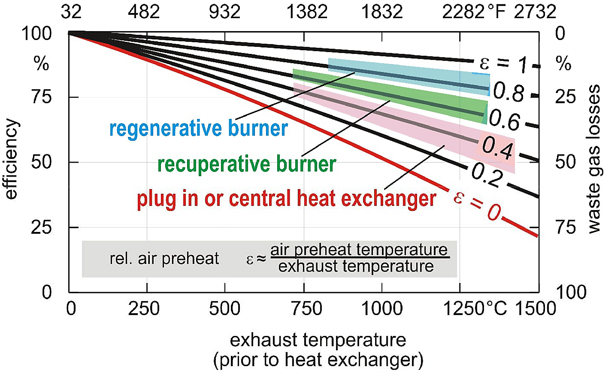
The curve labeled Ɛ = 0.4 represents a burner equipped with either a plug-in recuperator or a central heat exchanger. In this case, the combustion air is preheated to approximately 40 percent of the exhaust gas inlet temperature. At the reference temperature of 1,832°F (1,000°C), this burner type has an efficiency in the range of 60 to 65 percent.
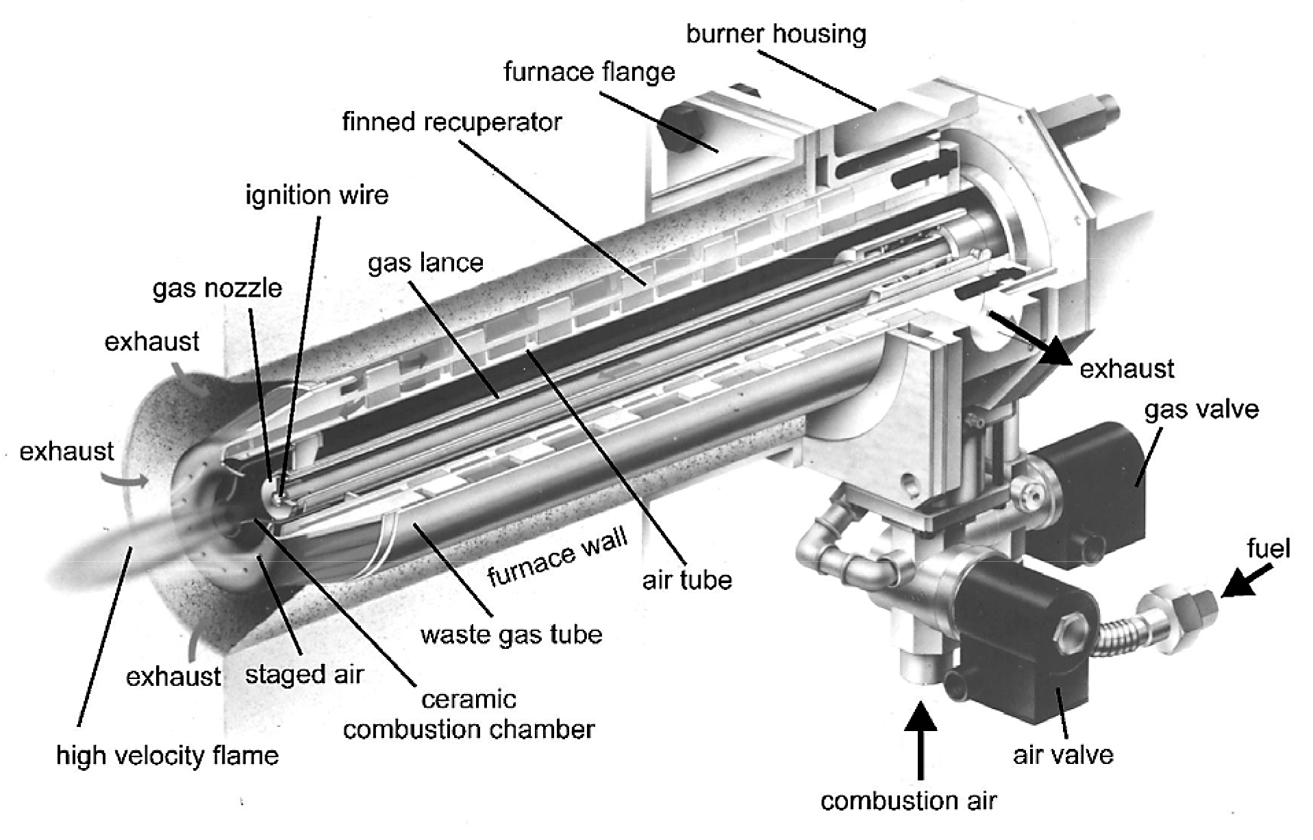
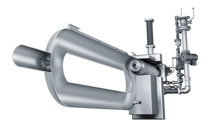
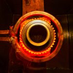
The curve labeled Ɛ = 0.6 represents a self-recuperative burner. With this burner type, the heat exchanger is an integral part of the burner, and it sits directly inside the wall of the furnace. This arrangement helps to minimize heat losses to the ambient and thereby provides increased efficiency. In this case, the combustion air is preheated to approximately 60 to 65 percent of the exhaust gas inlet temperature. At the same reference temperature of 1,832°F (1,000°C), this burner type achieves an efficiency in the range of 70 to 75 percent. Self-recuperative burners are available with either a metallic or ceramic heat exchanger. The metallic type can operate at temperatures up to approximately 2,050°F (1,120°C), whereas the ceramic type can typically operate at temperatures up to approximately 2,372°F (1,300°C). Figure 2 shows a cross-section of a self-recuperative burner.
NOx Reduction Techniques for High-Efficiency Burners
Traditionally, there has been a tradeoff between combustion efficiency and NOx emissions. In order to achieve high efficiency, it is necessary to preheat the combustion air to high temperatures. These high combustion-air preheat temperatures lead to high peak flame temperatures, which are the primary driver in NOx formation. NOx emissions are an exponential function of peak flame temperature, so they tend to increase rapidly with increasing furnace temperature and increasing combustion-air preheat temperature. There are a number of techniques available to help combat this problem.
One such technique is known as air staging. With this technique, a portion of the combustion air is mixed with all of the fuel to generate a partial reaction and release some heat. Then, the rest of the combustion air is introduced a bit further downstream to complete the reaction and release some more heat. In this way, the reaction is spread out rather than concentrated at one point. This serves to reduce peak flame temperature and thereby decreases NOx emissions.
High velocity combustion also serves as a NOx reduction technique. Mixing exhaust gases thoroughly inside the furnace or radiant tube has a temperature averaging effect. Therefore, peak flame temperatures are reduced, and NOx emissions are decreased accordingly.
Likewise, flue gas recirculation can also serve as a NOx reduction technique. Exhaust gases are very hot, but not as hot as a flame. So pulling a portion of the inert exhaust gases back into the flame front actually produces a cooling effect. This effect serves to lower peak flame temperatures and hence NOx emissions.
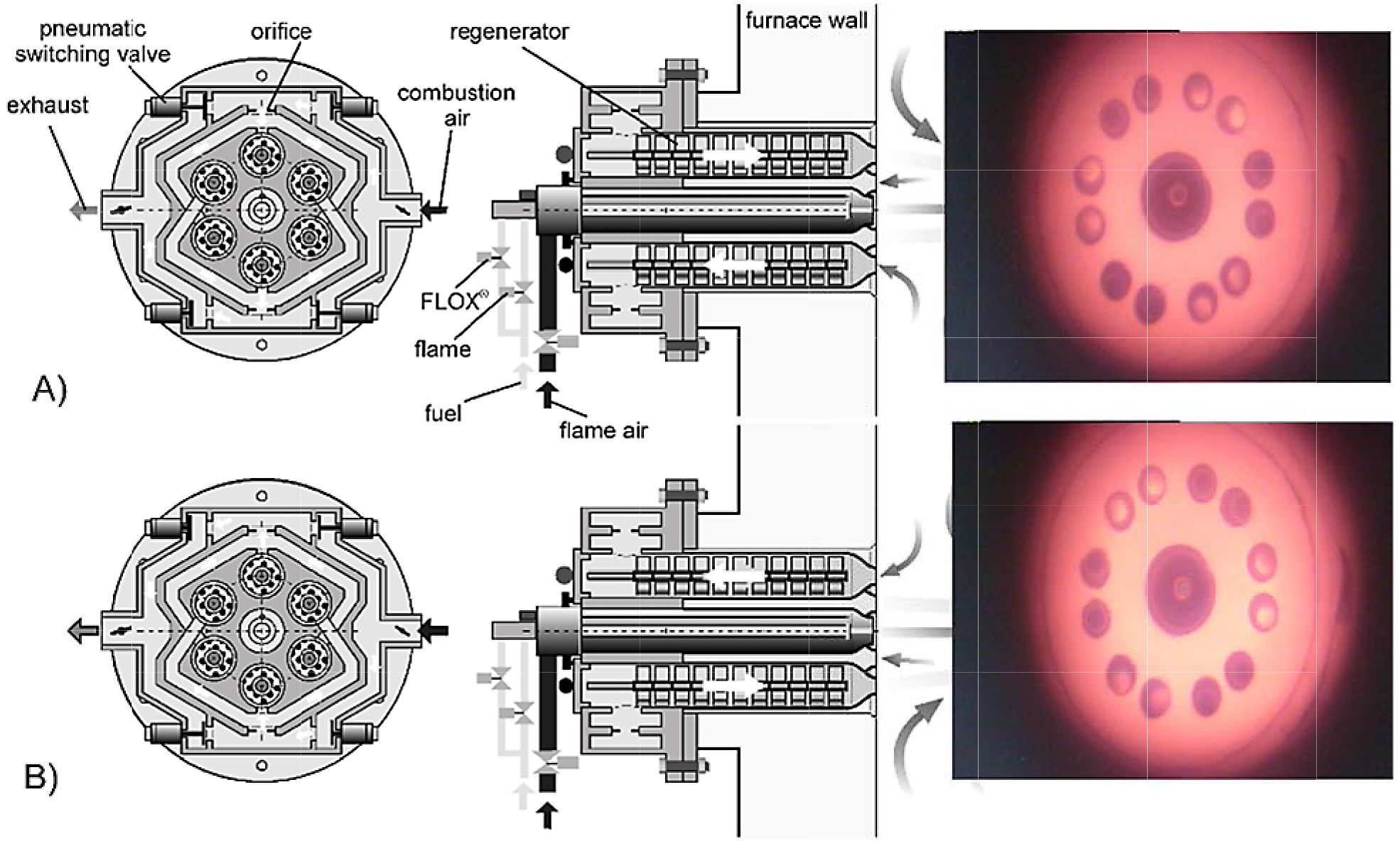
All of these techniques are quite effective under normal conditions. However, when combustion-air preheat temperatures reach very high levels, as in the case where self-recuperative or self-regenerative burners are utilized, the techniques are frequently not enough to reduce NOx emissions to acceptable levels. Fortunately, a revolutionary combustion technology has been developed to resolve this problem. This technology is known as FLOX® combustion, or FLameless OXidation [1], [3]. With this special technique, fuel and air are mixed with recirculated exhaust gases, and a spontaneous combustion reaction, which produces no visible flame, takes place. By eliminating the flame from the combustion reaction, peak temperatures are reduced dramatically, and this suppresses NOx emissions to a fraction of the level achievable with traditional NOx reduction techniques. This process only occurs above the auto-ignition temperature, and some safety factor is required; therefore, the FLOX® transition temperature is typically set at 1,550°F (850°C). Below this temperature, the burner operates in a normal mode of combustion with a flame. Once the FLOX® transition temperature is reached, the gas is injected in a way that produces a more favorable mixing/recirculation pattern and prevents flame formation and attachment. If the temperature drops below 1,550°F (850°C), the burner automatically reverts to “Flame” mode.
Radiant Tubes for Indirect Heating
In many cases, gas burners fire directly into the furnace chamber. In a number of cases, however, the process requires that work load not be exposed to the products of combustion. For example, some processes require a protective atmosphere, such as nitrogen, to prevent oxidation on the surface of the parts. In these cases, indirect heating is utilized. One method of indirect heating is to fire the burners into radiant tubes, which, in turn, transfer heat to the furnace and work load by virtue of a temperature differential.
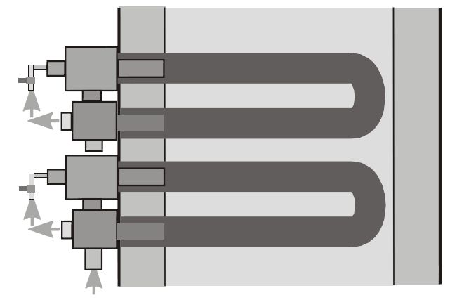
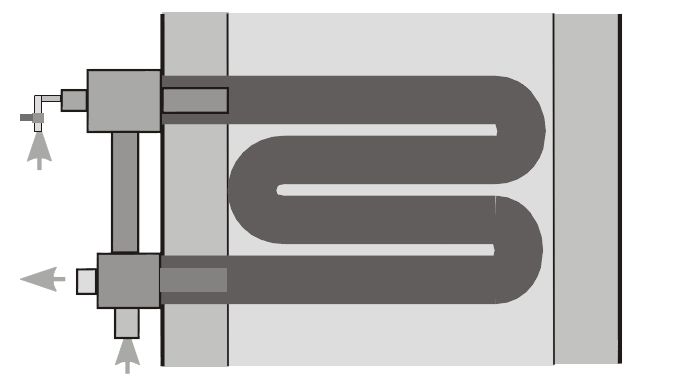
Cold-air burners, or those that utilize either plug-in recuperators or a central heat exchanger, are paired with traditional, non-recirculating-type radiant tubes. With this tube type, the burner fires into one end of the tube and exhausts out the other. Examples of this tube type are the U-tube and the W-tube (see Figure 5 and Figure 6).
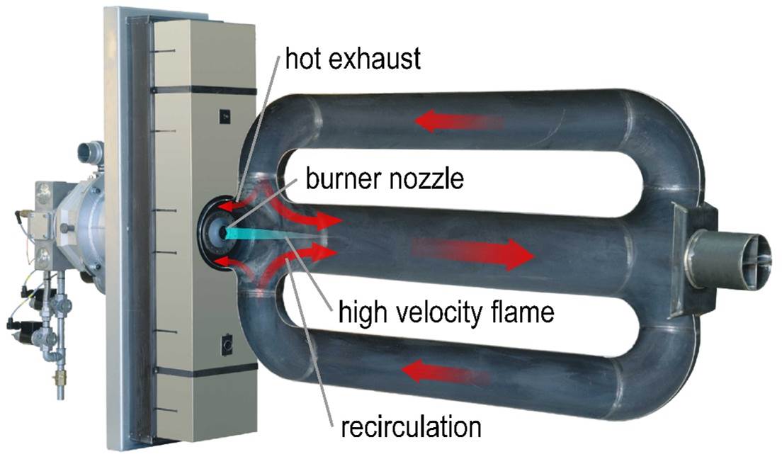
Self-recuperative and self-regenerative burners are paired with recirculating-type radiant tubes. These tubes each provide some sort of path for internal recirculation, and the burner fires into and exhausts out of the same end of the tube, leading to improved temperature uniformity over non-recirculating tubes.
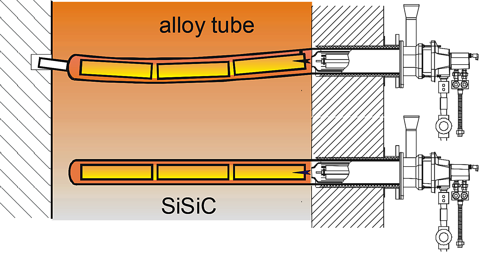
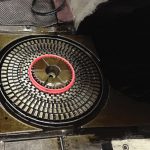
In the case of a single-ended radiant tube (see Figure 7), exhaust gases flow through an inner tube and then back toward the exhaust through the annulus between the inner and outer tubes. There is a critical space between the tip of the burner and the beginning of the inner tube assembly. The exhaust gases reach this point, and the high velocity burner jet creates a Venturi effect to draw a portion of the exhaust gases back into the inner tube. In this way, the exhaust gases are recirculated several times before they finally pass over the heat exchanger and out of a port on the burner.
Economics of High-Efficiency Gas Burners
Traditionally, when a company is contemplating whether or not to invest in new combustion technology, it is focusing on the payback time associated with the investment. The payback time is calculated by dividing the additional cost of the investment (over either the existing equipment or some baseline option) by the annual cost savings (usually as a result of mainly fuel savings). The result is a value expressed in years. Corporations normally consider a good investment to have a payback time of less than two to three years.
However, payback time alone is not a sufficient means to determine the viability of an investment. The net present value (NPV) is another important variable used by investors to make decisions. The NPV is the sum of discounted cash flows over a period of time, corrected to today’s value [4].
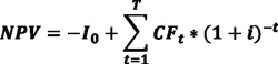 Equation 1
In this example, the NPV depends mainly on the generated fuel savings (∆CF), initial investment (I0), assumed interest rate (i), and assumed life span of the equipment (T). Simply, the investment with the highest NPV is the most advantageous. It is important to note that since the assumed interest rate (i) appears in the denominator of the equation, NPV is high when interest rates are low. Therefore, today is a great time to invest in new combustion equipment.
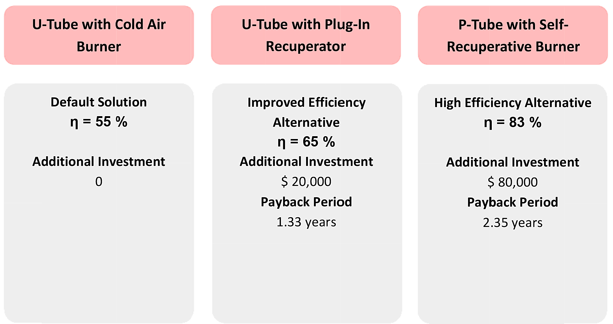
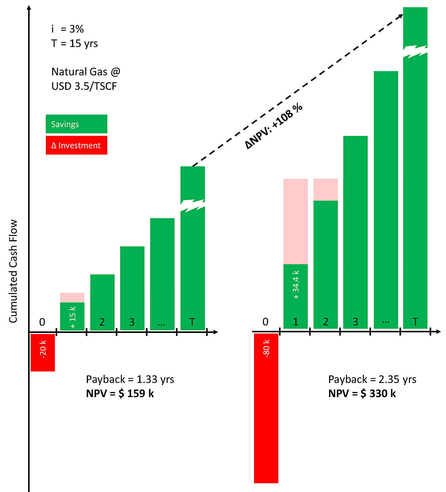
The example shown in Figure 10 and Figure 11 helps to further illustrate this point. The example assumes that new equipment will be installed and that the baseline equipment option consists of cold-air burners with U-tubes. The estimated efficiency is 55 percent, and there is no additional investment since this is considered the baseline option. The improved efficiency alternative is to add plug-in recuperators to the baseline equipment. The estimated efficiency for this alternative is 65 percent, and the additional investment is $20,000. This yields a payback time of 1.33 years in this example. The high-efficiency alternative is to use self-recuperative burners and P-tubes. The estimated efficiency for this alternative is 83 percent, and the additional investment over the baseline option is $80,000. This yields a payback time of 2.35 years. Therefore, the calculation of payback time alone suggests that the first option is the better investment. However, a comparison of the two investments over a period of 15 years shows that the NPV, and hence the cumulative cash flow, associated with the second option is more than double that of the first option. Therefore, the high-efficiency option clearly is the better investment even though the payback time at first suggests otherwise. This simple example shows how important a sound economic analysis is in order to make well-founded investment decisions. Due to the fact that the life-cycle costs of furnaces are mainly determined by the fuel efficiency, higher efficiency almost always pays off in the long run, even at today’s low energy prices.
Conclusion
The variety of burner types have varying levels of complexity and efficiency. Most high-efficiency gas burners preheat the combustion air to increase the combustion efficiency. Traditionally, there is a tradeoff between efficiency and NOx emissions; however, FLOX® combustion makes it possible to have the best of both worlds. As illustrated, the investment in high-efficiency gas burners makes sense economically even when gas prices are low. The lifetime savings generated by increased efficiency are significant, often five to ten times the additional investment. Also, for retrofits, increased combustion efficiency can increase the capacity of a furnace in many cases. From an economic perspective, a typical example shows that payback time alone does not provide sufficient information to make a well-founded investment decision. A sound economic analysis is necessary in order to choose the best heating alternative for a furnace.
References
- Joachim G. Wünning, Ambrogio Milani: Handbook of Burner Technology for Industrial Furnaces, 2nd Edition, Vulkan Verlag, 2015.
- Images provided by WS Wärmeprozesstechnik GmbH, Dornierstr. 14, 71272 Renningen, Germany.
- Joachim G. Wünning: Flameless Oxidation, 6th HiTACG Symposium, Essen, Germany, 2005.
- Uwe Götze, Deryl Northcott, Peter Schuster: Investment Appraisal – Methods and Models, Springer, 2010.


 general practice for CQI-9 and AMS2750E")


