


This study describes the influence of the steel characteristics of Ca-treated carburizing steel grades during hard part turning of synchronizing rings in gearbox production. The main focus was on the chemical composition of the non-metallic inclusions in the evaluated workpieces and their effect on the PCBN tool wear. In addition, a Ca-treated carburizing steel grade was compared to a standard steel grade. Machining tests were performed at the transmission machining site at Scania in order to evaluate the PCBN cutting tool life as defined by the generated surface roughness during actual production. The progression of flank and crater wear was evaluated by using a scanning electron microscope (SEM) equipped with an energy dispersive X-ray spectrometer (EDS) and a secondary electron (SE) detector.
The Ca-treated steel showed a more than doubled tool life than that of the standard steel grade. The superior machinability was linked to the formation of a Ca-enriched slag barrier composed of (Mn,Ca)S and (Ca,Al)(O,S). It is believed that the stability of the protective deposits is essential to minimize diffusion-induced chemical wear of the PCBN tool.
Background
Gearbox production of synchromesh rings, shafts, crown wheels, and pinions, among others, constitutes a number of manufacturing processes that are aligned in leveled and balanced flows. Typically, the flows are divided into soft machining, heat treatment, and hard machining. Examples of machining processes in a production line are turning, hob-milling, and drilling. Other common machining operations are deburring, grinding, and honing. A major challenge in transmission machining is to combine a high operating production efficiency, a high quality of the finished parts, a low tooling cost, and a robust production [1–5]. Therefore, the cutting tools and the workpiece materials used in transmission machining must be carefully adapted to the machining process and the workpiece specification.
Hard part turning is often the last machining process in a production line, and it aims at removing the final layers of the metal from the workpiece in order to produce the predetermined surface and geometry. The most frequent alternative to hard part turning is grinding, which is costly and leads to a reduced operating production efficiency. Moreover, cutting tools made of polycrystalline cubic boron nitride (PCBN) have been developed decades ago to machine hardened steel. In general, the PCBN is described as a super hard material, which gives an extreme yield strength also at high temperature [6]. The precise performance of a PCBN cutting tool in a defined machining process is given by the CBN composition, the CBN grain size, and the tool edge preparation [7-9]. In general, a high-PCBN cutting tool is composed of 70-90 vol% CBN, while a low-PCBN cutting tool has 50-70 vol% of CBN [10]. The remaining part is balanced by a metallic or a ceramic binder, like cobalt (Co) or titanium carbon nitride (TiCN), respectively. Previous research has shown that low-PCBN cutting tools have a longer service life than high-PCBN cutting tools [11, 12]. At the same time, low-PCBN cutting tools have been found to have a lower hardness and fracture toughness compared to high-PCBN cutting tools [10]. These contradictory results were explained by the interaction between the binder phase and the steel constituents of the workpiece, which resulted in CBN grain pluck-out and subsequent abrasive wear [13]. Another explanation is that the longer tool life of low-PCBN is attributed to its large bonding strength [14] and low thermal conductivity [15]. Thus, the heat generated at the tool edge-chip interface is transferred to the produced chips. At the same time, high-PCBN tools have a higher hardness and brittleness than low-PCBN tools. Thus, they are more prone to the elevated loads at the cutting edge [16].
In addition, it has been shown that a smaller average CBN grain size is beneficial for the resistance to an abrasive wear of PCBN cutting tools. It is due to an increased hardness and rupture strength of fine CBN grains. However, many research results are published on continuous hard machining, often at a laboratory scale, while less research is reported on intermittent machining, especially for production conditions. Even though there may be similarities, the machining conditions are different, which can effect the active tool wear mechanisms. Typically, the wear mechanisms of PCBN cutting tools are of an abrasive [17-19], an adhesive [20], a chemical [11], or a diffusive [21] nature. Frequently reported wear patterns are a flank and a crater wear, a micro-chipping, an edge fracture, and a nose wear.
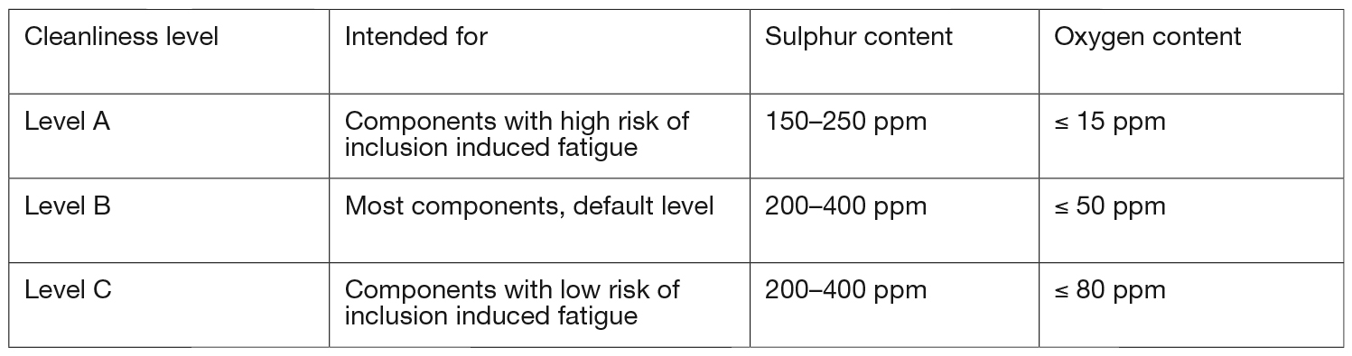
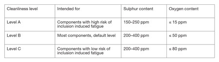
Carburizing steel grades are widely used in automotive production because of their excellent resistance to fatigue and due to their ability to carry high loads. In addition, carburized steel components have a typical surface hardness of 60 ±2 HRC, which levels out at 550 HV (~52.4 HRC) within a depth of 1 mm. Due to the risk for inclusion-induced fatigue of gearbox components at elevated stress values, the level of the steels’ cleanliness is of utmost importance. Thus, it must be secured to ensure a high-performance steel. Therefore, carburizing steel grades for gearboxes and diesel engines at Scania are classified into three levels, A, B, and C, based on their cleanliness level (see Table 1). Level A refers to high-performance steels, while Level B refers to a default level. Steel grades of Level C are rarely used and are solely selected if there is a low risk of an inclusion-induced fatigue. Additional requirements may be used to ensure a certain quality of a steel grade. For example, vacuum degassing, electromagnetic stirring, method of casting, reduction ratio, austenitizing temperature, hardenability, microstructure, and delivery state may be specified as a requirement for a specific steel grade.
Although the high-cleanliness steels have excellent mechanical strengths, the advantage has come at the expense of a reduced tool life and a more difficult chip breakage. In many applications, where a default type of steel is selected, a high production rate is the objective. For that purpose, many steel manufacturers have developed steels with improved machinability. High sulphur content as well as Ca-treatment are common means. Additions of calcium during deoxidation of liquid steel transforms hard Al2O3 inclusions into Ca-aluminates, which are softer and less likely to cause a cutting tool wear [22-27]. In addition, it should be pointed out that MnS and CaS inclusions are completely soluble with each other at the temperatures of a molten steel production [28]. Thus, it enables the formation of (Mn,Ca)S inclusions, which have a higher hot-hardness than pure MnS [29] inclusions. Therefore, complex (Mn,Ca)S inclusions are believed to be more abrasive than pure MnS inclusions. However, a successful Ca-treatment leading to a Ca-content of about 40 ppm requires a certain level of sulphur, typically around 300 ppm. Such machinability-improved, Ca-treated steel grades are fitted into the Level B of the steel qualities presented in Table 1. Therefore, they can be used to increase the production rate.
This work extends from a previous study where the influence of inclusion composition was linked to the tool wear during hard part turning of carburized steel by using a PCBN cutting tool [30]. It was found that Ca-treated steel showed a superior machinability in comparison to standard and clean steel. In addition, the machinability-improving effect of the Ca-treated steel was linked to the formation of protective slag deposits of (Mn,Ca)S and (Ca,Al) (O,S) that form on the rake face crater of the cutting tool. This study aims at clarifying the link between steel characteristics of the carburizing steels and the influence on the wear mechanisms and the cutting tool life in hard part turning of synchromesh rings during a gearbox production. In addition, the tool wear morphologies at different cutting speeds and frequencies of interruption were investigated. Here, a Ca-treated, machinability-improved steel grade was compared to a standard steel.
Experiment
Work Materials and Cutting Tools
Middle cones for a synchromesh gearbox were made of two carburizing steel grades. A standard carburizing grade of type EN 19MnVS6 was used as reference (R). See Table 2. The machinability-improved steel (M) was also of the type EN 19MnVS6. In addition to a relatively high sulphur content, the M-steel is Ca-treated to reach a 53 ppm calcium content. The two grades fit into the same classification with respect to the steel cleanliness standard of Scania.

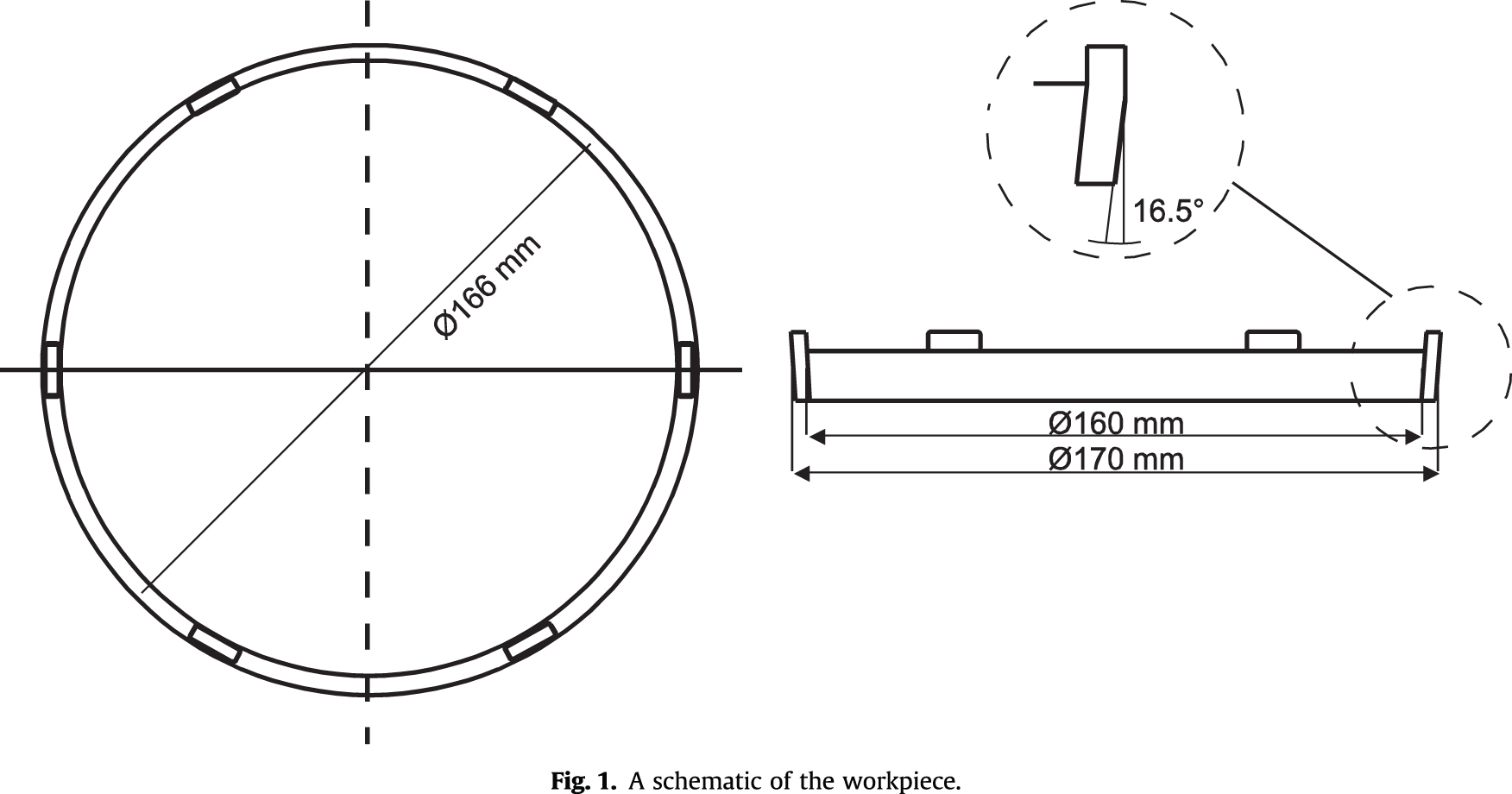
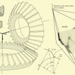
Middle cones (see Figure 1) of 170 mm in diameter were heat-treated as follows:
- Carburizing at 930°C for 3.4 h.
- Quenching in oil.
- Tempering at 195°C for 2 h.
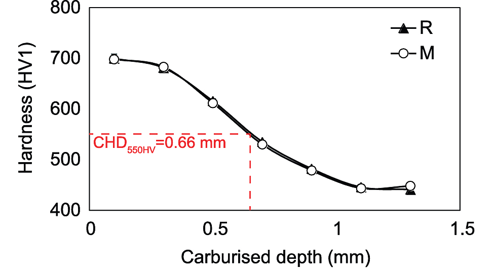
Hardness profiles including surface hardness and case hardening depth were measured using the Vickers hardness method (HV1).
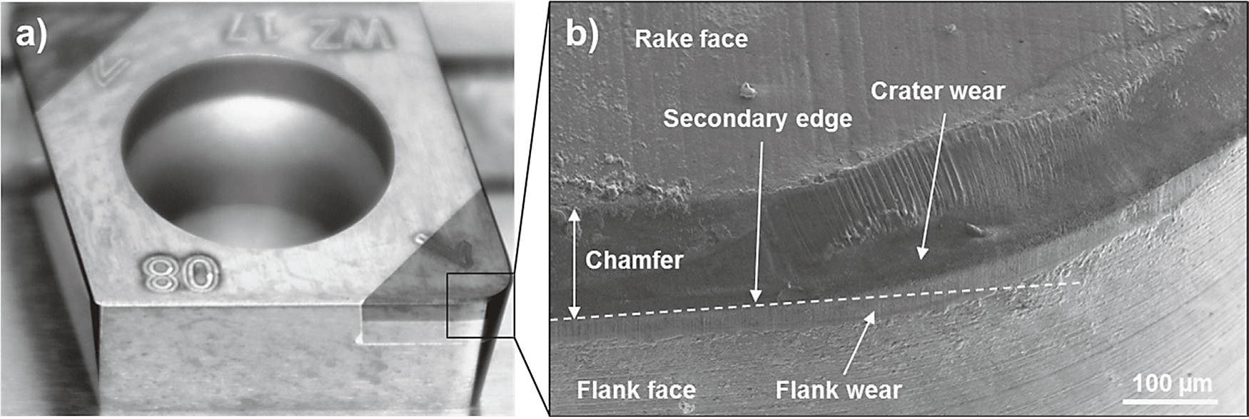
A SECO PCBN cutting tool with designation CCGW09T308S-01030-L1WZB, CBN150, was used in this work. The grade is made of a 0.45 volume fraction of CBN mixed with a ceramic binder composed of TiCN and Al2O3 and having an average grain size below 1 mm. The cutting tool has a 30° chamfer of width of 0.1 mm and a nose radius of rε = 0.8 mm (see Figure 2). In addition, it has a wiper geometry that is suitable for high feeding rates. At the current cutting speed of 166 m/min., the hard part machining engagement of each middle cone is about 11 s, which corresponds to a chip cut length (CCL) of 30 m.
Machining Tests and Tool Wear Monitoring
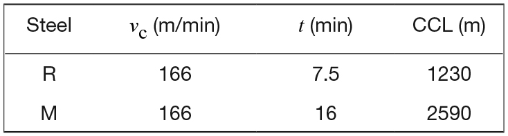
The machining tests were performed in an EMAG turning lathe under dry conditions. Tool life tests were performed by using a feed rate fn = 0.24 mm/rev., a radial depth of cut of ap = 0.15 mm, and cutting speeds of vc = 166-300 m/min. Most attention was paid to the tests at 166 m/min., which is the current cutting speed used in production. Three consecutive machining tests were included, which used both R and M-steel grades. The additional machining tests were made with an interruption prior to tool life aiming at studies of the initial wear mechanisms, as seen in Table 3. The tests duration corresponded to about 1/12 of their respective tool life. The test times were 7.5 and 16 minutes the R and M-steels, respectively. The corresponding chip cut lengths (CCL) were 1230 m and 2590 m, respectively.
The tool life criterion was defined as the surface roughness Ra ≥ 0.7 mm of the machined component or at a cutting edge failure. The surface roughness of the middle cone was recorded after completion of each machined component using a Mahr Perthometer S2. Therefore, a detailed tool wear analysis was conducted by using SEM with secondary electron (SE) imaging.
Analysis of Test Specimens
An inclusion analysis was undertaken by using scanning electron microscopy (SEM) in combination with energy dispersive X-ray spectroscopy (EDS). A back-scattered electrons detector was used with the SEM. Moreover, the investigated non-metallic inclusions were precipitated on a film filter surface after a completed electrolytic extraction of the steel specimens. The steel was dissolved by using a 10% acetyleacetone electrolyte and using an electric current of 40-60 mA.
Results
Hardness Profiles
The surface hardness of steel R and M was 698 ±4 HV (60.1 ±0.2 HRC), and the carburizing depth was 0.66 mm, as seen in Figure 3.
Inclusion Characteristics of the Evaluated Steels
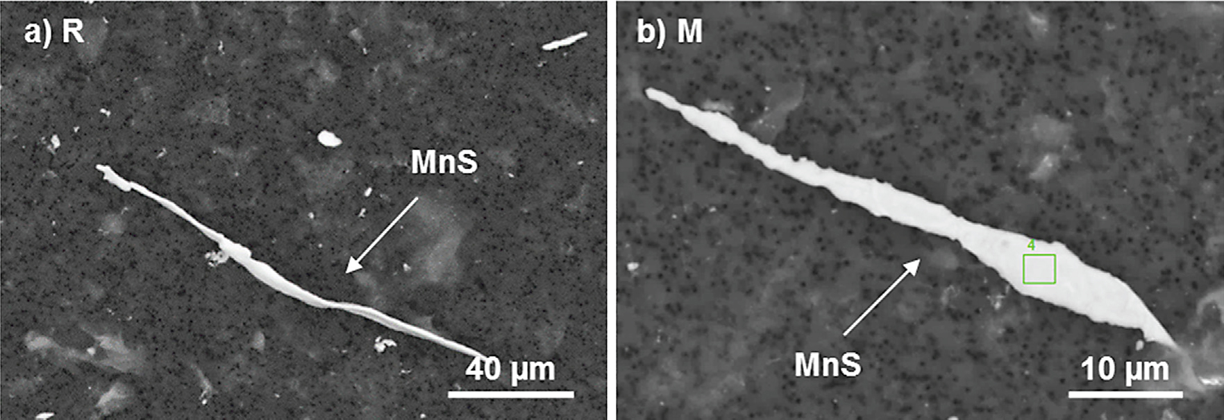
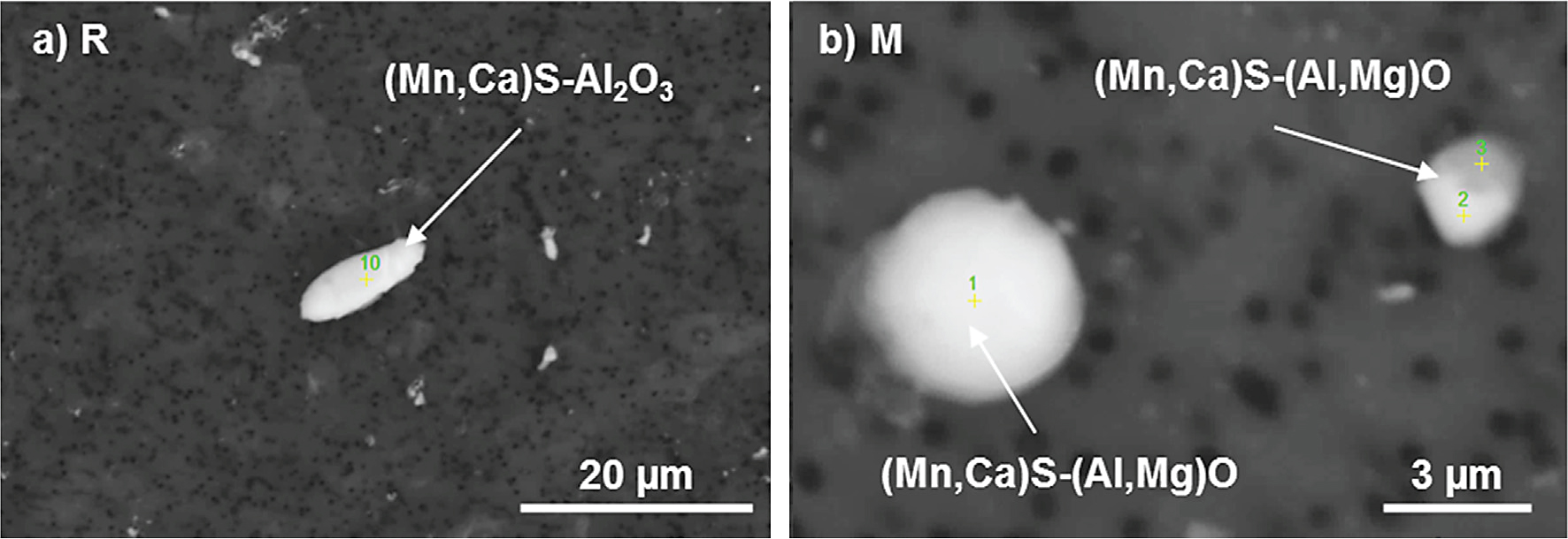
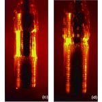
The reference steel grade R is characterized by MnS inclusions, which elongates during rolling to lengths greater than 100 mm (Figure 4a). Also, it contains less elongated (Mn,Ca)S-Al2O3 oxy-sulphides, which had a plate-like shape (Figure 5a) with a typical diameter of 10 mm. Similarly to the R-steel, the Ca-treated (modified M) steel grade contains elongated MnS inclusions with lengths of up to 100 mm (Figure 4b). In addition, the M-steel contains many fine and globular (Mn,Ca)S-(Al,Mg)O oxy-sulphides with a typical equivalent circular diameter smaller than 10 mm (Figure 5b).
PCBN Cutting Tool Life and Tool Wear
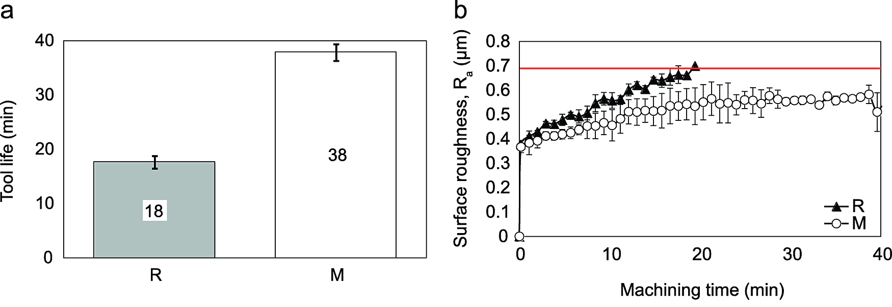
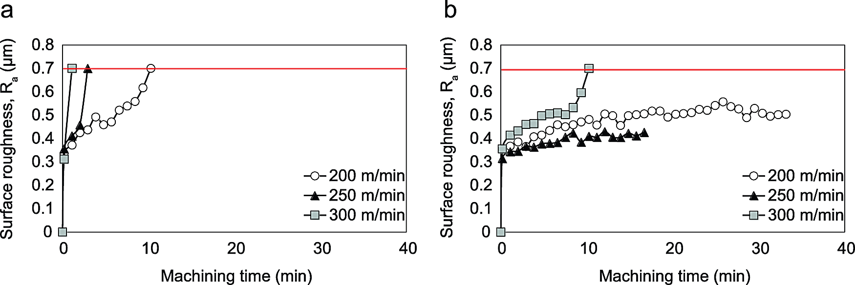
The M-steel shows a superior machinability compared to the R-steel; the corresponding tool life was 38 min. (CCL = 6300 m) and 18 (CCL = 3000 m), respectively, (see Figure 6a) for a cutting speed of 166 m/min. The tool life criterion of Ra > 0.7 mm was reached for the reference steel grade, while the test with the M-steel were halted due to distortions of the machined workpiece and chipping of the tool. The surface roughness (Ra) measurements indicate a smaller scatter when machining in the R-steel than in the M-steel (Figure 6b). Furthermore, the distinct difference between the two steel grades is that the generated surface roughness of the M-steel leveled out at about 0.5 mm, while the generated surface roughness of the R-steel displayed a progressive growth. The chip formation of both steel grades was acceptable. The chips were short and had an arc-like shape.
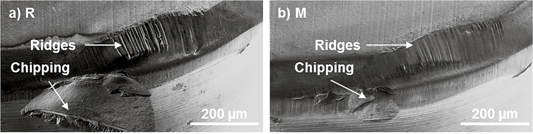
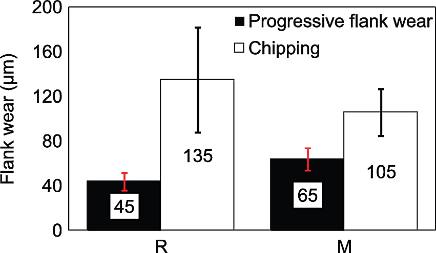
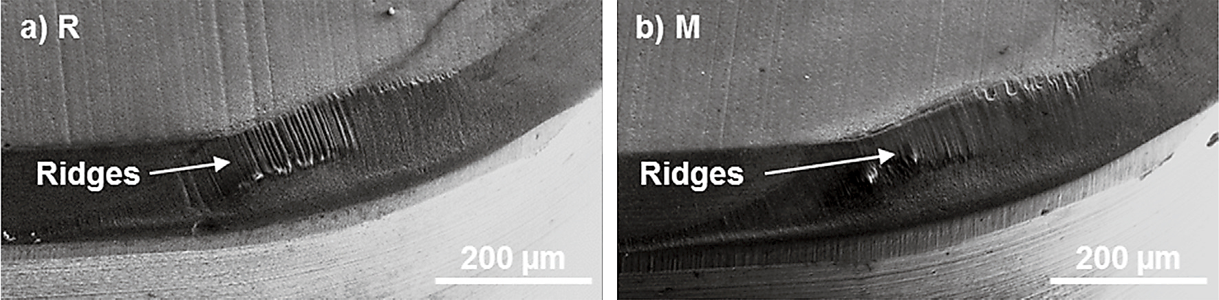
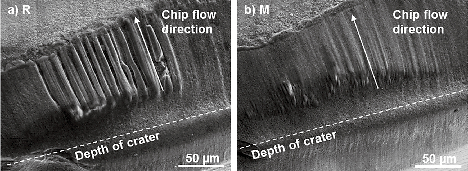
Although the R-steel and the M-steel generates an edge chipping at the end of the tool life, the tested PCBN edges have a well-balanced wear morphology consisting of a flank and a crater wear (Figure 7). However, note that the PCBN flank wear had progressed further at the end of the tool life of the M-steel (V = 64 ±10 mm) in comparison to the R-steel (VB = 44 ±8 mm). This follows the more than doubled service life of M. Typically, the R-steel generated chipping wear at an earlier stage, yet with significant scatter, as well as larger chippings, as compared to M, (Figure 7 and Figure 8). Moreover, a ridge formation was observed on the upper side of the rake face crater after a completed hard part turning of the steels. Also, the ridge formation was more pronounced after machining an R-steel than after machining an M-steel (Figure 7).
An investigation of increased cutting speeds showed that the cutting speeds of 200, 250, and 300 m/min. could be used with the M-steel with surface roughness below the Ra ≥ 0.7 mm criterion for 31, 11, and 6 min., respectively. The corresponding chip cut lengths were 6200, 2750, and 1800 m, respectively. In fact, only the test with the M-steel at 300 m/min. was stopped after 10 min. following the Ra ≥ 0.7 mm criteria. The tests at 200 m/min. and 250 m/min. did not exceed Ra ≥ 0.6 mm. Instead, they were stopped due to a shape change. On the contrary, it was only possible to machine the reference steel grade R not more than a 200 m/min. rate, which resulted in a tool life of about 8 min. (Figure 9). The cutting speeds of 250 and 300 m/min. resulted in an instant edge fracture when machining the R-steels. In addition, a more distinct ridge formation was observed in the rake face crater after a machining of the steels at the higher cutting speeds of 200-300 m/min. (Figure 10).
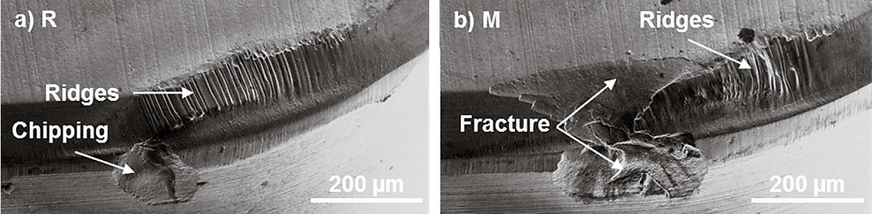
(8 min.) and (b) 300 m/min. (6 min.); the edges were etched prior to imaging
at (a) 41 parts (7.5 min.) and (b) 86 parts (16 min.); the edges were etched prior to imaging
Additional machining tests were undertaken and stopped prior to reaching the tool life. Tests were stopped at 7.5 min. (1230 m) and 16 min. (2590 m) for the R and M-steels, (see Figure 11). All cutting edges displayed a well-balanced flank and rake face wear, and no indication of chipping wear was found. However, a somewhat more advanced rake face wear was observed on the cutting tool tested with the R-steel in comparison to the M-steel. The flank wear progression was very similar in these tests. Moreover, the same tendency of a ridge formation on the upper part of the tool-chip contact zone on the rake face was observed with the R-steel (see Figure 7 and Figure 10).
Workpiece Material Adhered to the Cutting Edge
Transferred workpiece material was observed in the chip exit part of the rake face, after machining the R-steels (see Figure 12a). On the contrary, machining in the M-steel with a PCBN edge resulted in a minimum of material transfer to the rake face. Only small remnants of workpiece burr was found on the cutting edges, as given by Fe signals of the EDS analysis after machining both the R and the M-steels (Figure 12b).
at 41 (7.5 min.) and 86 parts (16 min.), respectively; obtained from the edges in Figure 11
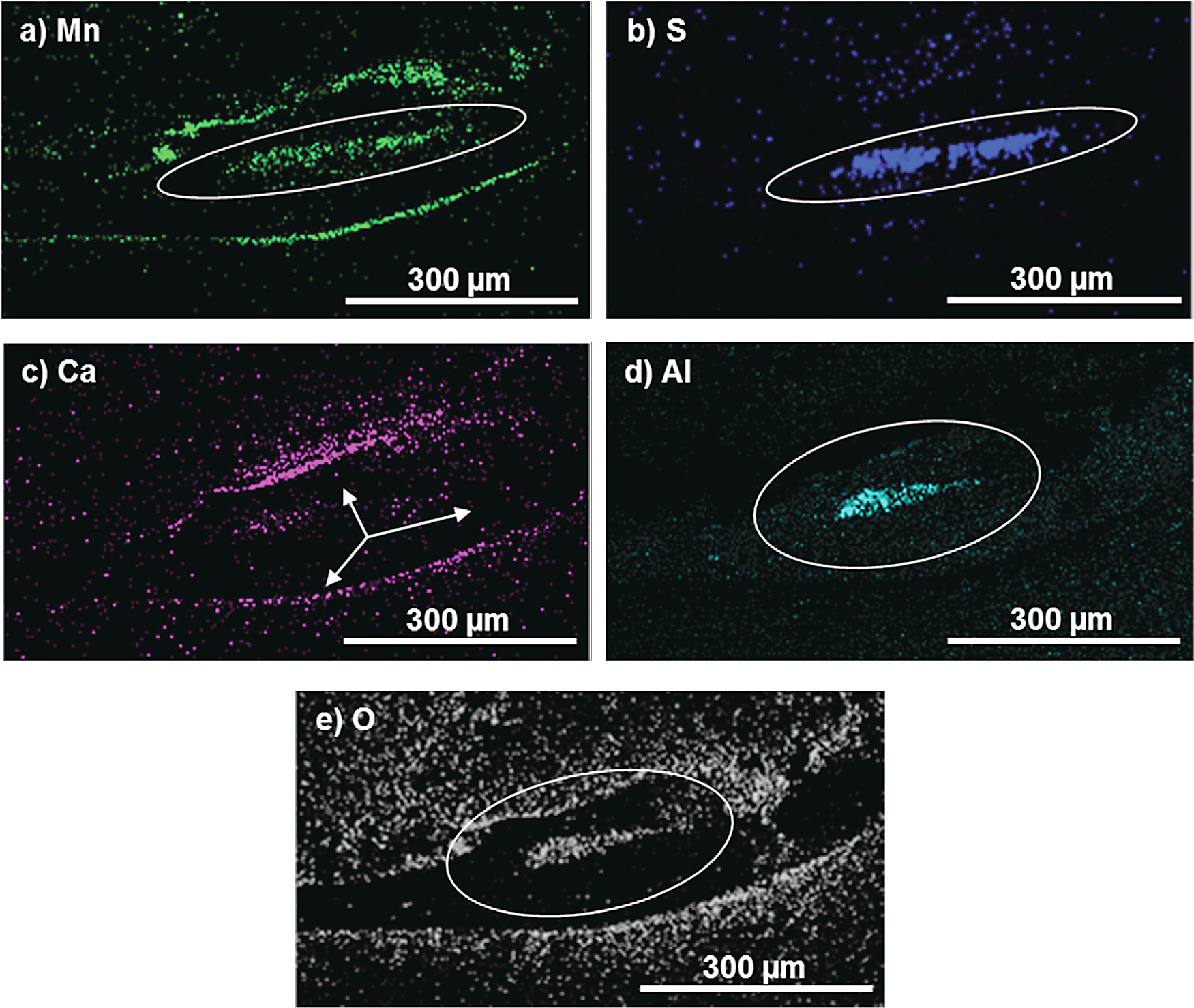
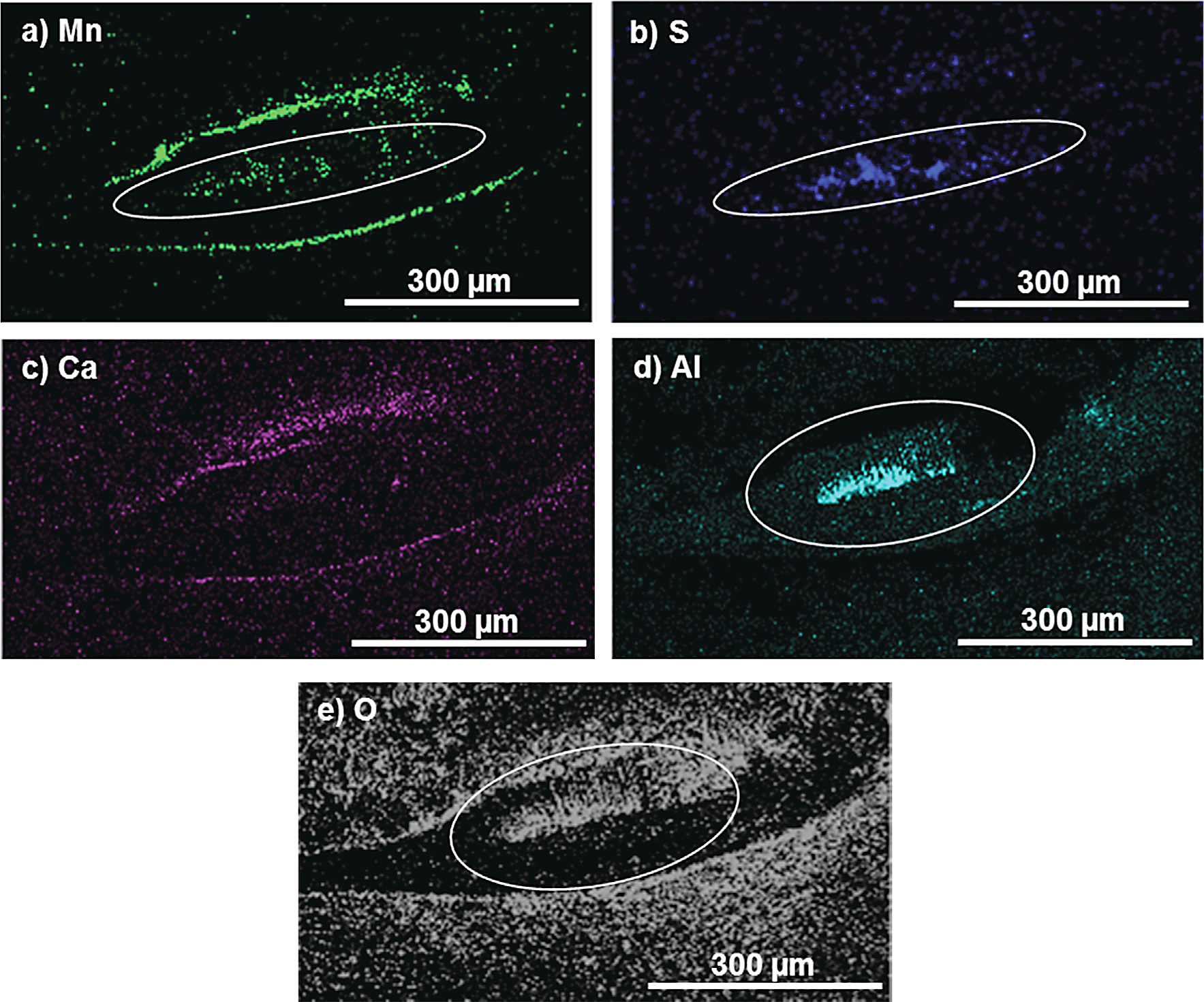
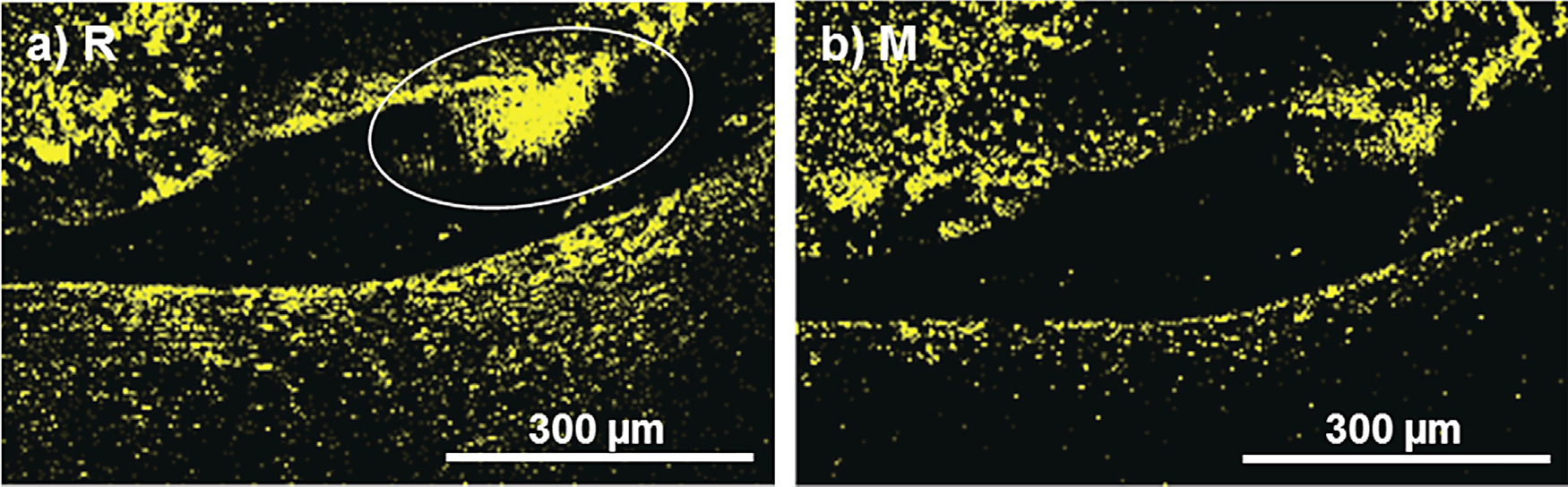
EDS of the M-steel crater indicated the presence of the slag elements Mn, S, Ca, Al, and O (see Figure 13). The segment rich in Mn and S has an elongated shape, parallel to the edge line. The elements Al and O were enriched in the ridges of the rake face crater and had a less elongated shape. Also, a low and even concentration of Ca is revealed in the crater (Figure 13c). Except for Al and O, much less slag deposits was found in the rake face crater for the R-steel compared to the M-steel, Figure 14.
Economic Impact
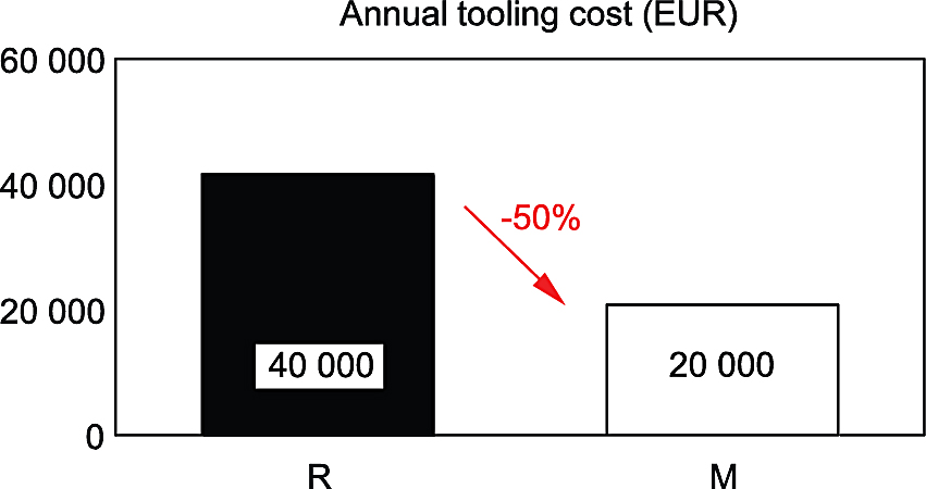
The annual production rate of middle cones at the manufacturing site is about 200,000 parts. The tested cutting tools from SECO have a listing price of about 42€ each. At the same time, the cutting tool life of the tested PCBN edges raised with about 110 percent at the evaluated cutting speed of 166 m/min. and the feed rate of 0.24 mm/rev. In total, this results in a reduced annual tooling cost saving of 50 percent, from 40,000 to 20,000€ (see Figure 15).
Discussion
The economic impact of an improved PCBN cutting tool life on gearbox production at Scania and purchase strategy: The more than doubled service life of the PCBN cutting tool in hard part turning of middle cones for gearboxes with the M-treated, machinability-improved steel enables an attractive annual tooling cost saving of about 50 percent, as compared to the R-steel, (Figure 6 and Figure 15). Moreover, even with the cutting speed increased from 166 to 200 m/min., the PCBN tool life with the M-steel was 31 minutes, as compared to 18 min. for the R-steel at 166 m/min. (Figure 6 and Figure 9). This corresponds to an increased service life of about 70 percent with the M-steel in terms of machining time, and actually about the doubled in terms of cut chip length. Consequently, the M-steel allows a significantly increased production rate.
The machinability-improved steel (M) corresponds to a Level B type of steel with respect to the cleanliness, (Table 1). The level B class is by far the most widespread cleanliness category used in transmission parts at Scania. Therefore, to introduce the M-steel on a wider range of components would lead to a significantly reduced manufacturing cost per produced component. In addition, the implementation of M-steels also has the potential to markedly increase the standard performance of the operating production efficiency and the production capability.
Tool life limiting wear modes: The surface roughness above the threshold value of Ra ≥ 0.7 mm was used as the tool life criterion in this study. In the reference turning operation of an R-steel at a 166 m/min. rate, the progressive flank wear had expanded to 44 ±8 mm, as based on three cutting edges analyzed. However, the flank wear given by the maximum extension of the edge chipping was 135 ±47 mm. Studies of the secondary edge showed that the chipping was actually located near the surface generating point on the secondary cutting edge, typically 150-200 mm from the nose. Therefore, the pronounced tool chipping tendency with the R-steel is believed to affect the generation of the workpiece surface significantly and consequently the tool life. The progressive flank face wear rate with the M-steel was lower than that of the R-steel, which indicates on a more easy-to-machine type of steel grade. However, the most valuable benefit with the M-steel in this study is the reduced expansion of the chipping on the flank face of the secondary cutting edge. The significantly reduced chipping wear made the Ra-value level out at 0.5 mm with the M-steel (see Figure 6b), i.e., below the tool life criterion. Consequently, the use of M-steels enables a significantly more robust machining process.
The general effect of non-metallic inclusions and the degradation mechanisms of low-PCBN cutting tool at hard part turning: PCBN tool wear in interrupted hard machining was studied during the gearbox production. It was found that the low-PCBN cutting tool (45 vol% CBN) failed, primarily due to an edge chipping and due to a crater wear during hard part turning of middle cones. Furthermore, this work shows that the PCBN cutting tool life during hard part turning depends on the formation and stability of the lubricating slag layers that acts as a barrier between the tool edge and the workpiece. It is relatively established in soft turning that calcium is enriched on the tool rake face and thereby has the ability to reduce the tool wear progression [31]. Furthermore, the analogous effect of the reduced wear on the rake face is obtained also during hard part turning, as shown recently by Ånmark et al. [30].
The current study confirms the strong positive effect of the Ca-based slag deposits formed on the tool edge and how they reduce the chemical degradation of the tool rake face. Moreover, the current study shows how the chipping wear can be significantly reduced by using a Ca-treated steel. It is proposed that the slag deposits detected on the rake face exist also on the edge line. However, the limitation of EDS analysis is of about 0.5 mm layer thickness; this does not show with this technique. It is proposed that slag deposits form also on the tool edge line and that they reduce adhesion and burr formation that may be the origin of the premature chipping behavior of the tests with the R-steel. This is of utmost importance for the tool life as it is defined by the component surface roughness. Since chipping wear is characterized by discrete and stochastic events, the reduced chipping is extremely important for the production robustness.
It is believed that the Ca-enriched barrier of slag deposits protects the tool against wear induced by a diffusion phenomenon in the tool-chip contact on the rake face of the PCBN cutting tool. Thus, this minimizes the material transfer to the PCBN edge. These findings agree with the EDS investigation, which only indicated a minor material transfer to the PCBN cutting edge after the machining of the R-steel and none after the machining of the M-steels. Without the lubricating slag layer, a higher friction between the tool edge and the chip flow is expected, which means a higher temperature at the tool-chip interface. Therefore, Fe-rich compounds from the chip flow may penetrate the tool surface and attack the CBN grains. It is easy to imagine an edge chipping of the PCBN tool if the CBN is depleted and replaced by Fe-rich compounds near the tool edge surface [13]. This phenomenon is believed to be promoted by a high temperature at the cutting edge, which is governed by an increased cutting speed [32]. The depletion of PCBN-cutting tools by Fe-rich compounds correlate well to the findings in a previous study where clean steels with a low content of non-metallic inclusions generated a significant amount of workpiece material (Fe) transfer to the PCBN cutting edge, coming from the chip flow and caused an edge chipping and a severe crater wear [30].
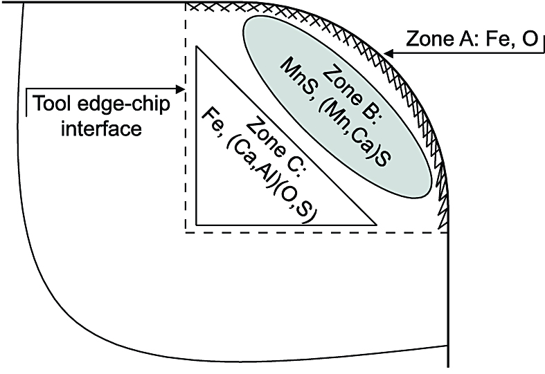
Distribution of slag deposits and the effect of calcium on the mechanism of ridge formation in the PCBN rake face crater: The improved machinability of the M-steel is linked to the Ca-enriched barrier of (Mn,Ca)S and (Ca, Al)(O,S) phases that are built up on the PCBN rake face crater (see Figure 13 and Figure 14) during hard part turning. Moreover, the EDS analysis showed that the steel constituents were transferred into different zones of the PCBN cutting edge as shown schematically in Figure 16. In Zone A, which represents the cutting edge, foremost the Fe and O contents are pronounced, especially when cutting in the R-steel. Zone B and C indicate the presence of Ca-enriched slag deposits. In Zone B, layers of MnS and (Mn,Ca)S phases were found. Typically, they had an elongated shape parallel to the edge line. In Zone C, a transferred layer of (Ca, Al)(O,S) was found together with Fe. The presence of (Mn,Ca)S and (Ca,Al)(O,S) phases in Zone C, at the rake face crater of the PCBN edge, is linked to the characteristic wear pattern of the ridges, as seen in Figure 7, Figure 10, and Figure 11 and the closeup picture in Figure 17. Similar results were obtained by Brion et al. in a previous study, where Fe and O were enriched in Zone A and C while Mn and S were more dominant in Zone B [33]. Without the Ca-treatment, no formation of the protective non-metallic inclusions will occur. This may lead to a faster degradation of the PCBN cutting tool as a consequence of a diffusion-induced chemical wear. Furthermore, it is believed that the PCBN ridges develop continuously during the intermittent machining operation and that the wear morphology becomes more apparent at higher cutting speeds. This is due to an increased interaction between the PCBN cutting edge and the chip flow.
Outlook on industrial use of Ca-treated steels: A large scale implementation of Ca-treated steels aiming at improved machinability requires extensive studies of how the material behaves through the complete manufacturing route, including rough turning, gear hobbing and drilling, heat treatment, distortion, hard machining, and grinding, etc. Positive results from studies of this scope make it possible to replace the current standard steels. These types of studies are dedicated for future work. Moreover, there is a multi-source requirement of steel suppliers that can offer Ca-treated steels with the desired steel quality.
The current study indicates that the use of a Ca-treated steel enables new possibilities in the optimization of productivity and robustness. The combination of a significantly reduced chipping wear on the flank face and the minimal crater wear on the rake face obtained with the M-steel in this study indicates that a higher CBN content tool grade can be used with this steel. High CBN content PCBN grades are often considered tougher, yet more susceptible to wear by chemical dissolution than that of the tool grade used in this study. An option with the M-steel would therefore be to not increase the tool life but to further reduce the risk of chippings and edge fractures. These phenomena are stochastic to their nature and undesired from a robust production point-of-view.
However, prior to a full-scale introduction of the Ca-treated steel two aspects must be dealt with: 1. The modified metallurgy of Ca-treatment must be verified with respect to the fatigue strength in component tests and compared to available data of the reference steel and specification. 2. There is a multi-source requirement of steel suppliers that can offer Ca-treated steels with the desired steel quality. Guaranteed deliveries from several suppliers and with repeatable properties is necessary to make use of the improved machinability of the M-steel.
Conclusions
The role of non-metallic inclusions on the tool wear and PCBN cutting tool life in fine machining of carburizing steel grades was investigated. A Ca-treated carburizing steel grade was compared to a standard steel grade. Furthermore, tool life tests were conducted in order to study the active degradation mechanisms at the end of the tool life. Also, additional machining tests were made with an interruption prior to the tool life aiming at studies of the initial wear mechanisms. From the findings in this work, the following conclusions can be made:
The hard part machinability of a standard carburizing steel (reference R) was improved by 110 percent by the Ca-treatment (modified M-steel). The improved machinability corresponds to a reduced tooling cost of 50 percent at the middle cone production of gearboxes at Scania. Therefore, to implement the M-steel on a wider range of components would be economically beneficial for the gearbox production at Scania. This can lead to a significantly reduced cost per produced component.
The most valuable benefit of the M-steel in this study is the reduced expansion of the chipping on the flank face of the secondary cutting edge and the more controlled progressive flank wear. Consequently, the M-steel enables a more robust machining process than the R-steel.
Thanks to its beneficial tool wear characteristics, a Ca-treated steel can be combined with a higher CBN content tool grade in hard part turning to further minimize the risk of stochastic chippings and edge fractures, thereby promoting the production robustness. It is believed that the Ca-enriched barrier of slag deposits protects the tool against a diffusion-induced wear at the rake face of the PCBN cutting tool. Thus, this would minimize the material transfer to the PCBN edge. In addition, without the lubricating slag layer, a higher friction between the tool edge and the chip flow is expected. This, in turn, means a higher temperature at the tool-chip interface. Therefore, Fe-rich compounds from the chip flow may penetrate the tool surface and attack the CBN grains, which will result in an edge chipping. It is also believed that the extremely thin slag deposits form also on the edge line and on the flank face. These films reduce the affinity of the tool-chip contact, and they impede transfer of workpiece material on to the cutting edge line, thereby explaining the reduced chipping wear in the machining tests with the M-steel.
The improved machinability of the M-steel is linked to the Ca-enriched barrier of (Mn,Ca)S and (Ca,Al)(O,S) non-metallic inclusions that is built up on the PCBN rake face crater during hard part turning. The presence of (Mn,Ca)S and (Ca,Al)(O,S) phases at the rake face crater of the PCBN edge generates a characteristic wear pattern of ridges. Without the Ca-treatment, no formation of the protective non-metallic inclusions will occur, which may lead to a faster degradation of the PCBN cutting tool as a consequence of a diffusion-induced chemical wear.
Acknowledgments
This work was funded by the unit of transmission machining at Scania CV AB.
This is an open access article under the Creative Commons (CC BY) license (creativecommons.org/licenses/by/4.0/) published by Elsevier B.V. Copyright 2016 The Authors. N. Ånmark and T. Björk. Wear, 368-369 (2016) 173–182. Available at: http://dx.doi.org/10.1016/j.wear.2016.09.016.
References
- F. Klocke, E. Brinksmeier, K. Weinert, Capability profle of hard cutting and grinding processes, CIRP Ann. Manuf. Technol. 54 (2005) 22–45, http://dx.doi. org/10.1016/S0007-8506(07)60018-3.
- K.K.B. Hon, Performance and evaluation of manufacturing systems, CIRP Ann. Manuf. Technol. 54 (2005) 139–154, http://dx.doi.org/10.1016/S0007-8506(07) 60023-7.
- N. Stricker, G. Lanza, The concept of robustness in production systems and its correlation to disturbances, Procedia CIRP 19 (2014) 87–92, http://dx.doi.org/ 10.1016/j.procir.2014.04.078.
- N. Stricker, A. Pfeiffer, E. Moser, B. Kadar, G. Lanza, L. Monostori, Supporting multi-level and robust production planning and execution, CIRP Ann. Manuf. Technol. 64 (2015) 415–418, http://dx.doi.org/10.1016/j.cirp.2015.04.115.
- H.G. Beyer, B. Sendhoff, Robust optimization – a comprehensive survey, Comput. Methods Appl. Mech. Eng. 196 (2007) 3190–3218, http://dx.doi.org/ 10.1016/j.cma.2007.03.003.
- P.J. Heath, Ultra-hard materials, Eur. J. Eng. Educ. 12 (1987) 5–20, http://dx.doi. org/10.1080/03043798708939332.
- J. Fulemova, Z. Janda, Influence of the cutting edge radius and the cutting edge preparation on tool life and cutting forces at inserts with wiper geometry, Procedia Eng. 69 (2014) 565–573, http://dx.doi.org/10.1016/j.proeng.2014.03.027.
- B. Denkena, A. Lucas, E. Bassett, Effects of the cutting edge microgeometry on tool wear and its thermo-mechanical load, CIRP Ann. Manuf. Technol. 60 (2011) 73–76, http://dx.doi.org/10.1016/j.cirp.2011.03.098.
- B. Denkena, D. Biermann, Cutting edge geometries, CIRP Ann. Manuf. Technol. 63 (2014) 631–653, http://dx.doi.org/10.1016/j.cirp.2014.05.009.
- Y.K. Chou, C.J. Evans, M.M. Barash, Experimental investigation on cubic boron nitride turning of hardened AISI 52100 steel, J. Mater. Process. Technol. 134 (2003) 1–9, http://dx.doi.org/10.1016/S0924-0136(02)00070-5.
- J. Barry, G. Byrne, Cutting tool wear in the machining of hardened steels Part II: cubic boron nitride cutting tool wear, Wear 247 (2001) 152–160, http://dx.doi. org/10.1016/S0043-1648(00)00528-7.
- Y. Huang, Y.K. Chou, S.Y. Liang, CBN tool wear in hard turning: a survey on research progresses, Int. J. Adv. Manuf. Technol. 35 (2006) 443–453, http://dx. doi.org/10.1007/s00170-006-0737-6.
- J. Angseryd, E. Olsson, H.-O. Andrén, Effect of workpiece sulphur content on the degradation of a PCBN tool material, Int. J. Refract. Met. Hard Mater. 29 (2011) 674–680, http://dx.doi.org/10.1016/j.ijrmhm.2011.04.016.
- W.Y.H. Liew, B.K.A. Ngoi, Y.G. Lu, Wear characteristics of PCBN tools in the ultra-precision machining of stainless steel at low speeds, Wear 254 (2003) 265–277, http://dx.doi.org/10.1016/S0043-1648(03)00002-4.
- K. Bouacha, M.A. Yallese, S. Khamel, S. Belhadi, Analysis and optimization of hard turning operation using cubic boron nitride tool, Int. J. Refract. Met. Hard Mater. 45 (2014) 160–178, http://dx.doi.org/10.1016/j.ijrmhm.2014.04.014.
- A. McKie, J. Winzer, I. Sigalas, M. Herrmann, L. Weiler, J. Rödel, N. Can, Mechanical properties of cBN–Al composite materials, Ceram. Int. 37 (2011) 1–8, http://dx.doi.org/10.1016/j.ceramint.2010.07.034.
- S.Y. Luo, Y.S. Liao, Y.Y. Tsai, Wear characteristics in turning high hardness alloy steel by ceramic and CBN tools, J. Mater. Process. Technol. 88 (1999) 114–121, http://dx.doi.org/10.1016/S0924-0136(98)00376-8.
- M.A. Davies, Y. Chou, C.J. Evans, On chip morphology, tool wear and cutting mechanics in finish hard turning, CIRP Ann. Manuf. Technol. 45 (1996) 77–82, http://dx.doi.org/10.1016/S0007-8506(07)63020-0.
- G. Poulachon, B.P. Bandyopadhyay, I.S. Jawahir, S. Pheulpin, E. Seguin, Wear behavior of CBN tools while turning various hardened steels, Wear 256 (2004) 302–310, http://dx.doi.org/10.1016/S0043-1648(03)00414-9.
- Z.N. Farhat, Wear mechanism of CBN cutting tool during high-speed machining of mold steel, Mater. Sci. Eng. A. 361 (2003) 100–110, http://dx. doi.org/10.1016/S0921-5093(03)00503-3.
- M. Zimmermann, M. Lahres, D.V. Viens, B.L. Laube, Investigations of the wear of cubic boron nitride cutting tools using Auger electron spectroscopy and X- ray analysis by EPMA, Wear 209 (1997) 241–246, http://dx.doi.org/10.1016/ S0043-1648(96)07488-1.
- R.V. Väinölä, L.E.K. Holappa, P.H.J. Karvonen, Modern steelmaking technology for special steels, J. Mater. Process. Technol. 53 (1996) 453–465, http://dx.doi. org/10.1016/0924-0136(95)02002-4.
- L.E.K. Holappa, A.S. Helle, Inclusion control in high-performance steels, J. Mater. Process. Technol. 53 (1995) 177–186, http://dx.doi.org/10.1016/ 0924-0136(95)01974-J.
- N. Ånmark, A. Karasev, P. Jönsson, The effect of different non-metallic inclu- sions on the machinability of steels, Materials 8 (2015) 751–783, http://dx.doi. org/10.3390/ma8020751.
- N. Ånmark, Inclusion Characteristics and Their Link to Tool Wear in Metal Cutting of Clean Steels Suitable for Automotive Applications, KTH Royal Institute of Technology, Stockholm (2015) http://dx.doi.org/10.13140/ RG.2.1.1958.3524.
- A. Nordgren, Tool Wear and Inclusion Behaviour During Machining of Ca- treated Steels, KTH – The Royal Institute of Technology, Stockholm, 1993.
- A. Nordgren, A. Melander, Deformation behaviour of different types of inclusion during chip formation in turning of quenched and tempered steels, J. Mater. Sci. Technol. 5 (1989) 940–951, http://dx.doi.org/10.1179/mst.1989.5.9.940.
- C.-H. Leung, L.H. Vlack, Solubility Limits in Binary (Ca,Mn) Chalcogenides, J. Am. Ceram. Soc. 62 (1979) 613–616, http://dx.doi.org/10.1111/j.1151-2916.1979. tb12743.x.
- C.-H. Leung, L.H. Vlack, Solution and precipitation hardening in (Ca, Mn) sul- fides and selenides, Metall. Trans. A 12 (1981) 987–991, http://dx.doi.org/ 10.1007/BF02643479.
- N. Ånmark, T. Björk, A. Ganea, P. Ölund, S. Hogmark, A. Karasev, P. Göran Jönsson, The effect of inclusion composition on tool wear in hard part turning using PCBN cutting tools, Wear 334–335 (2015) 13–22, http://dx.doi.org/ 10.1016/j.wear.2015.04.008.
- A. Larsson, S. Ruppi, Structure and composition of built-up layers on coated tools during turning of Ca-treated steel, Mater. Sci. Eng. A. 313 (2001) 160–169, http://dx.doi.org/10.1016/S0921-5093(01)00964-9.
- H.M. Lin, Y.S. Liao, C.C. Wei, Wear behavior in turning high hardness alloy steel by CBN tool, Wear. 264, 2008), pp. 679–684, http://dx.doi.org/10.1016/j.wear. 2007.06.006.
- J.M. Brion, B. Sander, G. Pierson, J. Lepage, J. Von Stebut, Mechanisms of built- up layer formation on turning tools: Influence of tool and workpiece, Wear 154 (1992) 225–239, http://dx.doi.org/10.1016/0043-1648(92)90156-3.


 general practice for CQI-9 and AMS2750E")


