


(Photo courtesy of Advanced Heat Treat Corp.)
Carburizing and nitriding treatments have the same goal: increase hardness on the surface while keeping the core ductility. Carburizing is a process where the part is placed in a confined environment regulated by its carbon content. By adjusting the parameters such as temperature and time, the carbon will diffuse into the part to a certain thickness. While the carbon content (%C) is fairly known at the locations where the carbon has diffused, it is harder to anticipate how far the carbon has diffused. The nitriding process uses the same concept but with nitrogen instead of carbon. The simulation of this process is helpful for the engineer to optimize the process. This article presents two examples to illustrate the carburizing and nitriding heat treatment processes.
Carburizing of a Bevel Gear
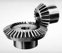
The bevel gear is a typical mechanical part produced in large quantities. This component will have to sustain continuous loading and unloading cycles generated by the contact with another moving metallic (hard) part (see Figure 1A). To avoid both damage of the surface and fatigue cracks, hardness on the surface and ductility in the core of the material are required.
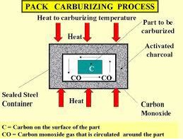
Although high-carbon steel would bring the requested surface toughness, fatigue properties would likely not be acceptable. On the other hand, low carbon could manage fatigue but marks would soon show on the surface. A possible solution to this dilemma is to use different carbon content on a different area of the part. This can be achieved through the carburizing process (see Figure 1B ). A low-carbon steel is maintained in a container filled with high-temperature carbon monoxide. After several hours, the carbon content increases on the surface area of the part, providing the expected properties.
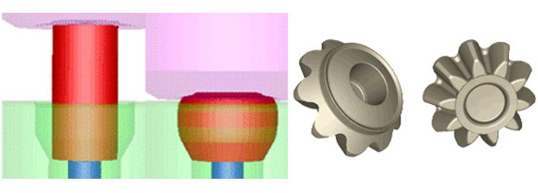
Net shape or near net shape is the forging of choice for such a part, which implies the use of a cold or warm forging process. In the presented example, the forging is a two-stage warm forging followed by the piercing of the central hole (see Figure 2). Simulations have been performed with Transvalor’s FORGE® simulation package. An elasto-visco-plastic material model was used, and flow curves come from JMatPro® simulation software (Sente Software).
The challenge for the simulation, apart from having the proper models to describe the diffusion of the carbon element into the part, is the software’s ability to refine the mesh in the areas where the diffusion occurs. The FORGE software’s unique capability to deal with large mesh with short computational time is key for this type of simulation.
At each time step, the carbon content is updated based upon the solution of a diffusion-type equation.
 Equation 1
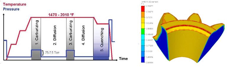
In Equation 1, C is the carbon content and D is the diffusivity, which varies as a function of the temperature. The input data used for the simulation setup are the furnace temperature and carbon content. Typical temperature cycle is shown in Figure 3, as well as carbon distribution at the end of the process.
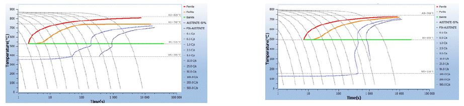
The increase in carbon content has a positive effect on the quenchability of the part. Figure 4 shows the quenchability difference between a 0.2% carbon steel and a 0.7% carbon steel content. As shown in Figure 4, for a 10-second cooling, a low-carbon steel (0.2%C) produces ferrite, then pearlite and Bainite, while a high-carbon steel (0.7%C) produces martensite only.
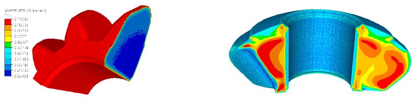
The result of the carburizing has been used as an input for the quenching simulation with heat transfer coefficients (HTC) corresponding to the typical oil quenching used for this type of bevel gear. The results show that the martensite phase has been created on the surface and other phases in the core (see Figure 5). Figure 5 also shows the residual stress (first principal stress) distribution after quenching, with blue showing the compression and red showing the tension.
- With the FORGE software, the evolution of metallurgical structures according to time is represented by a TTT (temperature-time-transformation) diagram. This diagram is obtained in an isothermal quenching condition. It gathers the curves that connect the corresponding points at each required temperature:
- Starting transformation time
- Ending transformation time
- Intermediate times corresponding to intermediate rates (10 percent, 90 percent)
In reality, quenching is never purely isothermal. The FORGE software uses an approach based on the additivity principle, which consists of breaking the thermal process down into elementary stages. The theory was introduced by W.I. Pumphrey and F.W. Jones and used by C. Aliaga. This approach, called “fictitious time,” separates incubation and growth. Growth will start when incubation, defined by the Scheil model, has ended.
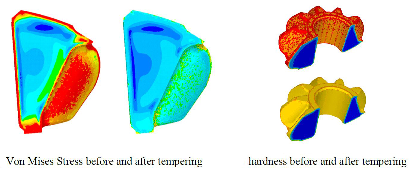
The last step of this study was the tempering. The purpose of this stage is to release residual stresses created during the quenching process. To achieve that, the part is held at a warm temperature (150°C to 200°C) for a certain time. A longer time in the furnace leads to higher temperature and homogenization of the temperature in the part, which in turn leads to higher efficiency for stress relaxation and hardness reduction. The objective of the engineer through the simulation is to find the right balance between hardness and residual stresses. To simulate this process, the Jaffe-Gordon tempering model has been implemented and coupled with material behavior adapted to a very low strain rate. Figure 6 shows the results obtained with typical time and temperature values. It can be seen that both stress relaxation and hardness decrease significantly.
Nitriding of an Aerospace Gear
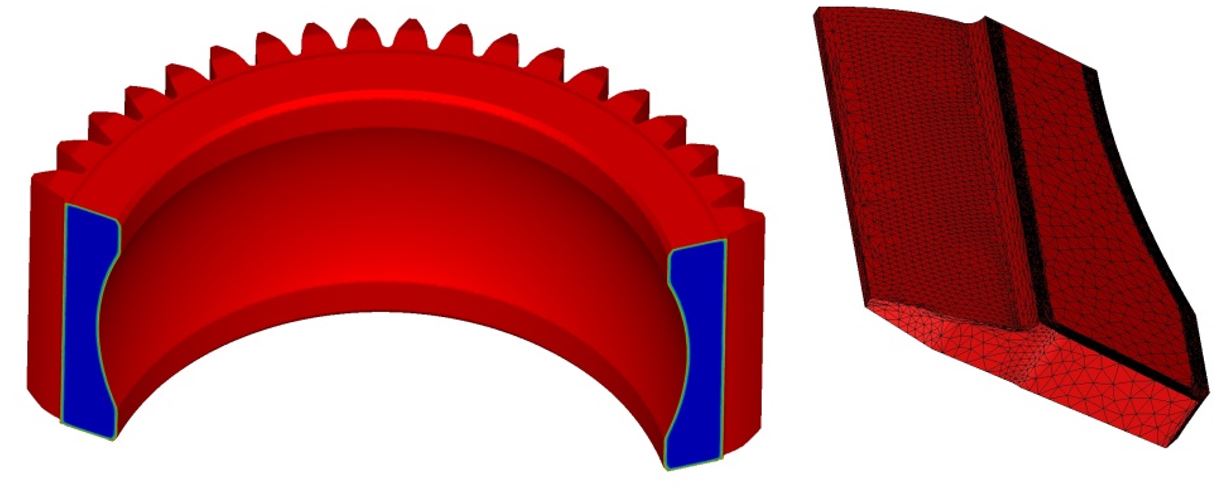
Nitriding can be applied on various metals under various conditions. It consists mostly in diffusing nitrogen into the surface of a steel part at about 550°C to harden the surface and improve its mechanical properties. This process has many advantages for fatigue, wear, friction, corrosion, and a relatively good assessment of the induced distortions. However, this process remains long and expensive, with about 100 hours of nitriding treating, less than 1 mm in depth.
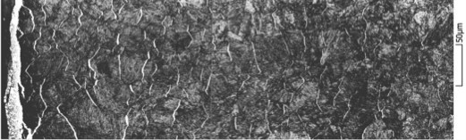
On the surface, a thin white layer from 0 to 30 microns composed of nitride ε and nitride γ’ is formed. Nitrogen diffuses from this white layer in a solid solution of ferrite to form what is called the diffusion layer, which is about 0.1 mm to 1 mm thick (see Figure 7). Some of this freely diffusing nitrogen element precipitates with various elements of the alloy, including carbon. The carbon diffusion plays an important role, even without carbon enrichment of the part. Because of nitrogen and carbon precipitates, the gradient created in the freely diffusing carbon generates a diffusion of the dissolved carbon, which can modify the chemical composition of the alloy at equilibrium. The presence of nitrogen precipitates is the reason for hardening and the generation of compressive stresses.
This study was part of the Definit project, which consisted of adapting the dedicated 1D nitriding simulation tool, developed at ParisTech university, to a fully industrial 3D simulation package (FORGE), and challenging against the experiments. For the finite element method (FEM) simulation, the problem is solved by adding several variables at each element: content of free nitrogen elements, free carbon elements (free means dissolved here, free to diffuse), and the content of phases and precipitates. The evolution of free carbon and nitrogen contents is computed at each node by solving two diffusion problems, described by the diffusion-type equation previously mentioned. C represents the chemical element concentration free to diffuse (carbon or nitrogen), and D represents the diffusivity.
 Equation 2
The composition of the metal in the element is computed depending on temperature, carbon content, and nitrogen content. Precipitates can form or dissolve, also modifying the free carbon and nitrogen contents. All data needed to compute the metal evolution can be obtained with JMatPro or ThermoCalc® software. The chemical composition computed at each mesh element enables local volume variation computation and hardness estimations. This type of computation, as explained earlier, requires a fine mesh in order to gather accurate results. In this example, the mesh size must be at least smaller than 0.2 mm for a 1 mm diffusion layer.
With courtesy of Airbus Helicopters (one of the partners in the Definit project), the results obtained on a fully nitrided gear are presented in Figure 8.
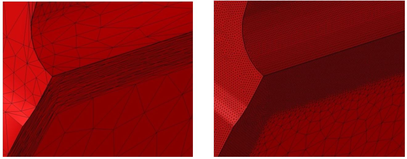
For the simulation standpoint, the anisotropic re-meshing is key to describe the phenomenon occurring within the diffusion layer. With the automatic re-meshing technique available in the FORGE software, a mesh size of 0.05 mm can be reached for a total of 22,000 nodes in the mesh. In comparison, 1.5 million nodes total with an isotropic mesh would be needed to obtain the same precision. Figure 9 shows the comparison of meshes, with the anisotropic mesh on the left and the isotropic mesh on the right-hand side.
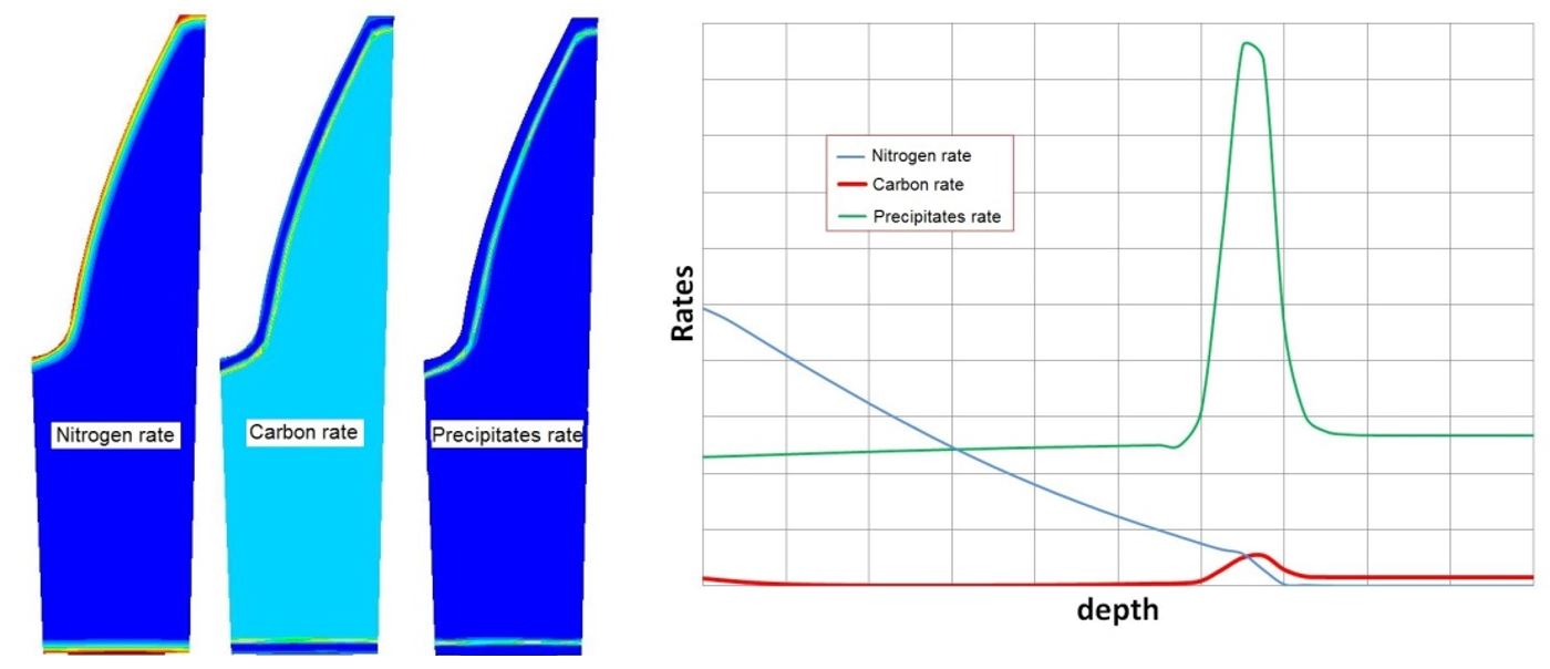
With the results of the free carbon and free nitrogen diffusion in the material, the new chemical composition of the metal and the presence of precipitates in the diffusion layer can be computed. Figure 10 shows the carbon, nitrogen, and precipitate contents as a function of depth in the graph with the location of each component on the left-hand side.
Conclusion
The benefits of simulation for forging processes are no longer challenged in the industry. After decades of development, forging is fairly well-simulated, but new challenges have emerged. The microstructure of the final parts is a crucial aspect of the forging that industrial manufacturers must master in order to compete. The weight reduction of the transportation systems is a major challenge for the forging industry, and the margin reduction prohibits the traditional trial and error on the shop floor. Simulation is the only way to obtain quick responses to these challenges with limited investment.
The two industrial studies presented here have been performed with the commercial software FORGE. It shows that developments from the research have been implemented successfully and are now available for industrial manufacturers. New projects will lead simulation to new challenges that will need to be tackled through shared efforts from the research and the commercial simulation software vendors.


 general practice for CQI-9 and AMS2750E")


